This thread has been locked.

If you have a related question, please click the "Ask a related question" button in the top right corner. The newly created question will be automatically linked to this question.

UCC27211: Full bridge gate driver has a different behavior during phase control with high loads(approx 7W)

Part Number: UCC27211
Other Parts Discussed in Thread: , UCC27201A,

Tool/software:

Hi,

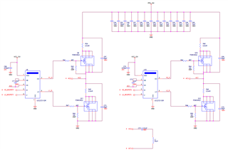
My full bridge inverter using the above mosfet driver and the mosfet used is FDMC8622, during the phase control my gate drive output and the inverter outputs are misbehaving and inverter is not functioning as expected.

This behavior is not seen with low loads less than 100mA during the phase mode. Images are attached for reference.

During the issue case my gate driver U9 output is going to low even my gate driver input is high.

The reference point AC2 is also behaving same as gate driver output. the other end of inverter AC1 doesn't have any issue only at the AC2 end and its high side drive output is having issue.

The inverter is operated at 160Khz phase starts at 135 degree and can go up to 0 degree based on load change or power requirement.

  • Hey,

    Thank you for reaching out to TI with your question regarding the UCC27211.

    I have a few questions to help me better understand your system and the situation that you are seeing.

    1. Can you please share a scope capture of HB-HS, HO-HS, HS-VSS, and HI-VSS?

    2. Can you please take another scope capture showing HO-HS, HI-VSS, VDD-VSS, and HS-VSS?

    3. What is the amplitude of your HI/LI signals and can that be increased?

    It appears there is some significant noise on the measurements taken. In order to verify if the noise is seen in the system or just a result of measurements, please take the measurements using a tip and barrel probe and take the measurements as close to the pins of the gate driver as possible.

    Let me know what your responses to the above are and if you have any further questions.

    Thank you,

    William Moore

  • Hi William,

    As you requested captured the above signals with minimal ground loop.

    1. 'NonWorking_capture-1' contains HB-HS, HO-HS, HS-VSS, and HI-VSS.

    2. 'NonWorking_capture-2' contains HO-HS, HI-VSS, VDD-VSS, and HS-VSS.

    3. Amplitude of HI/LI signals are fixed at 3.3V from FPGA, and cannot be increased.

  • Hey,

    So there seems to be some noise on HB and HI. One thing that can help with this is to increase the gate resistance. This could be as much as 10-30ohms.

    Another option is to try the more noise immune UCC27211A. That was the major improvement in the "A" version of the UCC27211. It appears that you are using the D package version of UCC27211 which we do not have for an industrial version on UCC27211A. We do have the DDA package in the automotive version (UCC27211A-Q1). Another option for D package is the more noise immune UCC27201A.

    Let me know if you have any questions.

    Thank you,

    William Moore

  • Hi William,

    I will try both suggestions and let you know the results.

    1. But still my doubt is why gate drive is going to zero even if the driver input is high, i have not seen any UVLO conditions. As you said is it because of HI noise? if possible can you clarify.

    2. I was suspecting that the load transition from 125mA to 1.25A  during the full bridge phase control mode the inverter is not able to supply enough power, so the AC signal was going to  zero. And we saw this issue only when the inverter is operated at full bridge phase mode, it may recover after some time if we continue power transfer. Please comment you thought on this.

    3. We saw VCC of UCC27211 was dipping during this issue case, and i have increased the decoupling capacitor from 4.7uF to 9.4uF, then VCC became stable. The datasheet recommends 4.7uF, but is there any problem if we use more than mentioned in the datasheet?.

    4. Bootstrap capacitor- what will happen if i use higher value than the datasheet recommended?. and is my issue is related to bootstrap capacitor?

    please clarify the above doubts.

  • Hey,

    1. If there is enough ringing on the rising edge of HI, it could oscillate above and below the high threshold causing the driver to interpret the signal as not above the threshold.

    2. Are you saying this scenario only occurs under no load, or light load conditions?

    3. It is okay to have a decoupling capacitor that is greater than that of the datasheet. Just ensure that it is X7R ceramic.

    4. You may be on to something here. It may be that this value of bootstrap capacitor is too small and not able to sustain the output current needed for the gate drive. You could try values from 100nF up to 1uF and be okay with you current decoupling capacitor of 9.4uF.

    Check out this App Note regarding selecting bootstrapping components such as capacitors to help with sizing these capacitors discussed above.

    Bootstrap Circuitry Selection for Half-Bridge Configurations

    Thank you,

    William Moore

  • Hey,

    Do you have any updates, further questions, or responses to my above questions?

    Or have you been able to resolve this issue?

    Thank you,

    William Moore

  • Hi William,

    Sorry for the delayed reply.

    With the gate resistor change the issue got resolved.

  • Hi William,

    Sorry for the delayed reply.

    With the gate resistor change issue got resolved, thanks for the support.