This thread has been locked.

If you have a related question, please click the "Ask a related question" button in the top right corner. The newly created question will be automatically linked to this question.

LM7481: MOSFET failure

Part Number: LM7481
Other Parts Discussed in Thread: LM317, ,

Tool/software:

Good day,

We are experiencing a problem with the way we use the LM74810 power path controller. Please see attached schematic.

VAUX and VBAT are 2 power supply/battery inputs, 24V typical. V_MOTOR is connected to motor driver ICs. Control logic is powered from VAUX.

We use LM74910 to choose the power supply for the motor, our choice does not depend on which supply is higher. We choose with VAUX_EN and VBAT_EN (driven by 3V3 processor). In our application VAUX_EN and VBAT_EN are never on at the same time. Switchover time between logic signals VAUX_EN and VBAT_EN is ~20us.

Our experience is that even without high currents in the system (motors always off), Q2 or Q7 fails short. We measure the MOSFET body diode drop, then we switch between VAUX and VBAT several times, and some time later Q2 or Q7 measures 0V/short for the body diode.

Do you have any insight into what we might be doing wrong?

Kind regards


lm74810_query.pdf

  • Hi Marius,

    Looks like there is a MOSFET SOA failure.

    Are you turning on the downstream load during startup?

    Please use this tool to design your startup.

    FET-INRUSH-SOA-CALC Calculation tool | TI.com

    Regards,

    Shiven Dhir

  • Hi Shiven,
    Thank you for your input.
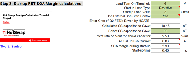
    I have filled in the calculator spreadsheet Steps 1&2. I wasn't quite sure about step 3. The tutorial that is linked in the spreadsheet shows different parameters, ie is a slightly different spreadsheet.
    There is a fair amount of capacitance to handle. V_MOTOR has another 3500uF on it (thus total about 4000uF). There is another 2200uF downstream of an LM317, whose current limit I expect to regulate the inrush current into that capacitor.
    On power up both LM74810 are off and the logic section is powered from VAUX via D3.
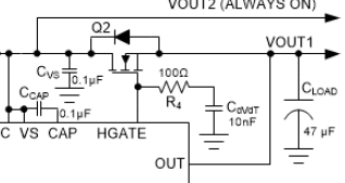
    I used Cdvdt = 10n and R=100R from the example in the datasheet
    but it seems I neglected the large amount of capacitance on the output.
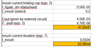
    In what I hope are correct spreadsheet calculations, I can see that for the implemented circuit (Cdvdt=10nF), the inrush current is in the 20A range.
    Our application is not sensitive to how long it takes to turn on, so it appears I could easily make Cdvdt=47nF and reduce the inrush current to 5A.
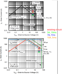
    Please see below image. The top shows SOA for the used Q2, the bottom shows SOA for an alternative. On each I show the relevant points for the 4 inrush current examples calculated above (I use 30V, circuit max).
    My interpretation is that the used Q2 is outside of SOA for all inrush current examples. For the alternative part the existing circuit is borderline, but lower inrush currents are well within SOA.
    My questions to you:
    • Is my interpretation correct, should the circuit be good with Cdvdt=47nF, t_inrush~10ms, using the alternative FET?
    • What is a sensible upper limit on the value of Cdvdt?
    • Are there any considerations when making the inrush time longer?
    • What effect does the series resistor (100R in the datasheet example) have/ what effect does changing the value have?
    • Can you please indicate how to use section 3 in the FET-INRUSH-SOA-CALC Calculation tool | TI.com (I unfortunately couldn't figure out how to attach my example file to this response)
    Thank you and kind regards,
    Marius
  • Hi Maurius,

    1. Yes, your interpretation is correct. It can work with less amount of current.

    2. I would not recommend to go more than 0.1uF on CdvdT

    3. FET SOA margin and startup time are the only considerations

    4. 100ohms resistor limits the current into the CdvdT. Discharge of that cap also depends on that resistor. 100ohms is a good value.

    5.  In step 3, you are expected to enter the details of the startup. As in, at what VOUT, you will start drawing load. What is the profile of load (resistive or constant current). This is an important step to know if your design will pass the startup. SOA margin is recommended to be >1.3.

    Regards,

    Shiven Dhir

  • Hi Shiven,
    Thanks again for your input.
    Regarding your numbered list:
    2) What are the considerations when exceeding 100n for Cdvdt?
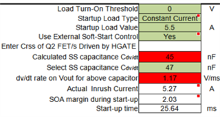
    5) I notice that for 'startup load value' your spreadsheet has 'Ohms', the one I downloaded has 'A'.
    Please see below. Firstly, why are the two cells red (seems like no matter what value they have, they remain red)? Secondly, why is the result for startup time almost twice the value when calculated using the datasheet eqns?
    Is there a reference for the design equations used in the spreadsheet?
    Thank you and kind regards,
    Marius
  • Hi Marius,

    2. When we cross 100nF of Cdvdt, we need an extra local discharge network. Usually, Cdvdt is discharged into the controller. But when the cap is 0.1uF, energy is higher and discharging it into IC can damage it.

    5. Spreadsheet has a changeable load type, constant current / resistive due to which the units are changed. Please share your calculator with me to review it.

    Regards,

    Shiven Dhir

  • Hi Shiven,

    Apologies for delay on my side. We have ordered parts etc. in the meantime.

    Regarding the points:

    2) You have previously said "I would not recommend to go more than 0.1uF on CdvdT", which implies that 100nF is still ok. In the previous post you said "But when the cap is 0.1uF, energy is higher and discharging it into IC can damage it", from which 100nF is already too high, possibly damaging the IC. What is the safe upper limit on Cdvdt to guarantee not damaging the IC?

    5) Please see attached spreadsheet for the implemented calculation.

    LM74810_inrush.xlsx

    Kind regards,

    Marius

  • Hi Marius,

    At 47nF- 68nF, the device is guaranteed to not damage. Although this doesn't necessarily mean you need to use 68nF. You have to look for the sweet spot for inrush current vs time to be in safe SOA. 

    Regards,

    Shiven Dhir

  • Hi Shiven,

    I have run some tests using the alternate MOSFET (see my post June 17, 7:51 AM for original vs alternate MOSFET SOA).

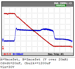
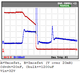
    My test setup turns the load switch on for half a second, and then off for 15 seconds. An added load resistor (only part of the test setup) discharges the load capacitors when the load switch is off. I have also added an extra 1200uF capacitor in parallel with the load capacitance to ensure some headroom for a successful solution (Cbulk+= 1200uF in the  images below). The red trace A shows the voltage across the MOSFET, the blue trace B shows the voltage across a 20mOhm current sense resistor in the power supply path.

    For Cdvdt=20nF, it was fine at first until I went from Vin=30V to Vin=32V

    2 questions about this:

    • from the SOA of the alternate MOSFET, it should not break, but still does. What could be the cause?
    • when it does break, I would have expected it to break later in the pulse, when it has absorbed at least a similar amount of energy to the first pulse. But it breaks a lot earlier. Why is that?
    • I tried a making Cdvdt=47nF, which roughly halves inrush current and doubles the inrush time. However, the MOSFET still broke, and I would really have expected Iinrush ~5A to be ok given the SOA of the used MOSFET.

    Do you have any additional insight into how to fix this?

    2 small peripheral points:

    • equation (7) in LM7481-Q1 SNOSD98A – MAY 2020 – REVISED DECEMBER 2020 uses the number '12'. I blindly used the same number in my calculations, where it should be 32V. If there are constants in an equation, I assume they are either the result of physical constants or device specific/unchangeable numbers. Perhaps eqn 7 could be recast using 'Vin', 'Vbatt' or similar.
    • where can I find out more about LM7481 internal circuitry, specifically regarding the Cdvdt pin where you have mentioned that external circuitry would be required for Cdvdt>100nF?

    Kind regards,

    Marius

  • Hi Marius,

    That 12 just comes for a 12V system from the equation I=Cdv/dT. In your case it will become 32 instead of 12. Which is like almost 3 times more.

    There is nothing much about the internal circuitry, its just that the energy is pretty high in a 100nF cap charged to 30V as it has to ultimately discharge into the controller. If we add a local discharge network, we can add higher Cdv/dT also.

    If you are running very high value COUTs, stronger FET is required or very low Inrush current for very long duration can help. 

    Regards,

    Shiven Dhir

  • Hi Shiven,

    Thanks for your continued support.

    1. Why is the FET I am using not strong enough? I appear to be using it within the SOA.
    2. This is the strongest 60V FET I could find (stongest here meaning highest acceptable DC current within SOA). Do you have a stronger suggestion?
    3. Can you please share the schematic for the local discharge network? In case I need Cdvdt > 68nF.

    Kind regards,

    Marius

  • Hi Marius,

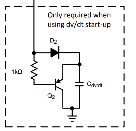
    Local discharge network looks like this. Although just for evaluation, you can keep your Cdv/dt as 0.1uF also. Repetitive ON/OFF is a problem for the controller. You can test the startup without this network also.

    Regards,

    Shiven Dhir

  • Hi Shiven,

    1) Please see my attached calculation spreadsheet.
    I have used SLVA673A and followed the calculations for the 48-V, 20-A PMBus Hot Swap Design in section 3.2.
    For the example calculation in the spreadsheet, I get the same values as SLVA673A (just as a check for my eqns in the spreadsheet).
    Then I do the same calculations for my application. My interpretation is that if the result in the green cell is less than the result in the light orange cell (25 degrees) and the dark orange cell (for 85 degrees ambient), the FET should be within SOA.
    Is this interpretation correct?


    lm7481_mosfet_soa.xlsx


    Despite my experiments all using a 25 degrees MOSFET, with no load (other than the capacitive load of the circuit) and a 15s period between switch off and switch on, they still break, despite my inrush current being significantly lower than the SOA current.
    What considerations am I missing?

    2) In moving from this circuit

    to the one with external discharge,

    R1 in my discharge circuit (which is not in the appnote) would offer some protection for Q1 as C1 becomes larger.

    You have previously said: "100ohms resistor limits the current into the CdvdT. Discharge of that cap also depends on that resistor. 100ohms is a good value."

    1. In the appnote discharge circuit, R1 into C1 is not present. How is the current limited in that case?
    2. To keep the shut-off time for HGATE low, I would want to make R1 lower if C1 becomes larger. Is there a lower limit for R1 when charging C1 from the LM7481? For discharge, Q1 handles it.

    Kind regards,

    Marius

  • Hi Marius,

    What is the total capacitance in your test setup?

    1200uF + load capacitors. Can you mention the total COUT?

    Regards,

    Shiven Dhir

  • Hi Shiven,

    The circuit has about 4800uF of load capacitance. For testing, I have added 1200uF in parallel.

    In the spreadsheet, I use a value of 6000uF.

    Kind regards,

    Marius

  • Hi Shiven,

    Just another thought. You have mentioned that 100R for R1 in series with Cdvdt is a good value. Where does the 100R come from?

    The only thing I see is from the HGATE parameters, where sink current is ~200mA (and no maximum is given). Using a typical value of Vsupply=12V -> V_HGATE~23V, we then have 23V/100R=230mA. I assume the HGATE discharges to GND via LM7481.

    You also mentioned that adding a local discharge network is required because the energy discharged into the controller becomes too high with larger C1.

    What about using a higher resistor value for for R1 to limit the discharge current into the controller to acceptable values for larger values of C1?

    If that is viable, what are the design equations?

    Kind regards,

    Marius

  • Hi Shiven,

    It is becoming a bit urgent from our side to conclude this, I would like to ask you to please respond to open questions.

    When using high values for Cdvdt, what are the limiting factors for the value of R1?

    I have run tests with different values for Cdvdt and R1, up to 80 degrees ambient.

    If I use Cdvdt=220nF and R1=280R, do you see any problems for the LM7481?

    I will probably use R1=470R.

    (There is no way to integrate the discharge circuit onto the existing PCB.)

    Kind regards,

    Marius

  • Hi Marius,

    Resistor in the path of CdvdT is to limit the current into the controller during discharge and not limiting the current into the capacitor. Sorry for error before.

    Higher resistor will have one downside and that is during turn-off, if the controller is turned on again at very short interval, Cdvdt will not be discharged fully, and inrush current might not be controlled as expected. It is better to add a local discharge circuit as it will discharge the Cdvdt instantly and fast ON/OFF will have no issue.

    Regards,

    Shiven Dhir

  • Hi Shiven,

    Thanks again for your response, but I do not feel that my question is being addressed.

    You have mentioned previously that R1 is required to limit the Cdvdt discharge current into the controller, and that "100R is a good value". You have also mentioned that Cdvdt~68-100nF is the upper limit for Cdvdt because of what the controller can handle.

    From you previous comment "But when the cap is 0.1uF, energy is higher and discharging it into IC can damage it." I take that R1 needs to be larger to ensure that the IC is not damaged.

    If I need Cdvdt > 100nF to manage inrush current in my case, I assume I need to make R1 larger to make the discharge current lower.

    So my question is:

    For Cdvdt > 100nF, how do I find the smallest acceptable limit for R1? (without using the additional discharge circuit)

    Kind regards,

    Marius

  • Hi Marius,

    Apologies for the misinformation. As stated, the resistor is used to limit current in discharge state. I will check with the designer to know how high the resistor needs to be to avoid the local discharge network. 

    Just bringing to your attention again that increasing the resistor will slow down the discharge and rapid turn-on/off of the controller will not limit the inrush current as CdVdT will stay charged.

    Regards,

    Shiven Dhir

  • Hi Shiven,

    Can you please let us know when we should expect a response to our query from August 26?

    Kind regards,

    Marius

  • Hi Marius,

    For Cdvdt of 220nF, you can use 470R

    Regards,

    Shiven Dhir