Tool/software:
hi,
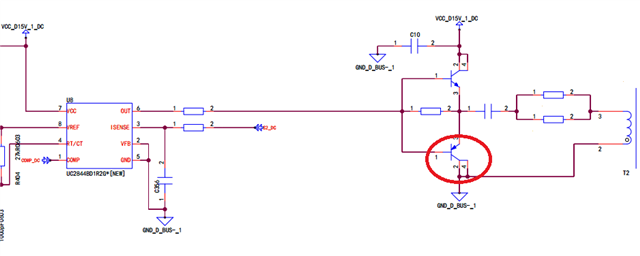
Pls refer to the schematic of UC2844. -0.7V can be captured on OUTPUT pin of UC2844. Would you like kindly help check if this -0.7v on OUTPUT pin will lead any risks? would like evaluate whether this behavior will cause the 2844 to work incorrectly or inefficiently? If not, what is the approximate maximum reverse voltage of the OUTPUT port?
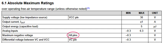
According to UC2844 datasheet. -0.3V is the maximum voltage.
The -0.7v is generated because:
A set of push-pull tripolar is driven by the 2844 and the N-tube is switched off and on to the P-tube when the OUTPUT output is switched from high to low. In this process, however, the primary side inductance of T2 requires a continuous flow, so a continuous flow circuit is formed through the 2 1 pin of the red-circle PNP BJT.
So the 2 1-pin PN junction drop of 0.7V is added to the output port of UC2844 to form a stable -0.7V.