This thread has been locked.

If you have a related question, please click the "Ask a related question" button in the top right corner. The newly created question will be automatically linked to this question.

BQ25756: Problems with custom charging board

Part Number: BQ25756

Tool/software:

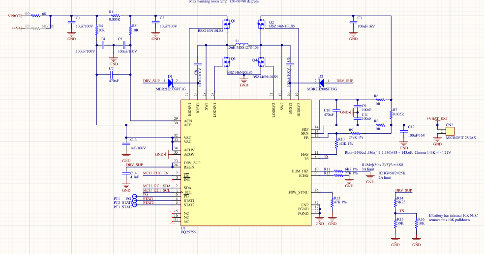
I developed a charging board using BQ25756 and I set current charge limit to near 2A (27K resistor at ICHG pin) and protection current set to 3A (ILIM with 6K8 and 5mOhm probe between ACN and ACP).

The battery is charging but with only 0.5A, not 2A as expected. At ICHG pin I can see a waveform close to a senoide with 2V of peak and 17KHz. Is normal see a pulsed signal at this pin, some advice that what can be happening?

  • Hello Leonardo,

    Thanks for working with us on this. I've got a few questions to help us debug this.

    For your tests, what's your input voltage and battery voltage?
    Are you seeing the same oscillation on the battery voltage as well?

    Best Regards,
    Ethan Galloway

  • I'm working with LiPO battery 4.2V (4000mAH), 1-cell. Input voltage for charger is from 9 to 32V, but I'm doing the tests mainly with 12V (at 24V behaviour is similar).

    I need operate just foward (buck).

    At battery, I see a ripple of 100mVpp, with same frequency (17KHz). STAT1 pin is low, PG pin is low, showing me that charge is working. I really see the voltage of battery increasing, just the current is much lower than I have set.

    I expect at ICHG pin a DC level voltage that reflects charge current, but I see a quasi senoidal waveform of 2Vpp (17kHz). At ILIM pin I see 0V all the time.

    Leonardo

  • Hello Leonardo,

    Thanks for being patient with the wait. I have a few suggestions for your schematic.

    The charger needs 80µF on VIN and BATT for stability. I recommend adding more capacitance to the VIN side of the charger. I would also recommend adding HF caps close to Q1 and Q2 to filter out high frequency noise.

    When the ICHG resistor is less than 5kΩ, we recommend the installation of a RC filter in parallel with the resistor.

    Let me know if those adjustments work for your board.

    Best Regards,
    Ethan Galloway

  • I reduced the input capacitors because I was thinking that 80uF is necessary when in reverse mode. Usually buck converters don't need too high input capacitance. I'll try your suggestions and post results here.

    More one question, about RC filter in parallel with ICHG, which is the recommended value? Does this apply to ILIM too?

    Best regards,

    Leonardo

  • Hello Leonardo,

    Thanks for being patient with the delay. I was out of office Thursday and Friday.

    Yes, we recommend using an RC filter in parallel with the ILIM resistor when the ILIM resistor is greater than the 5KΩ. For the RC filter, I recommend copying the values on the EVM.

    Also, there's a typo in my previous post. I meant to say to use a RC filter when the resistor is greater than 5kΩ not less than 5kΩ.

    Best Regards
    Ethan Galloway