Because of the holidays, TI E2E™ design support forum responses will be delayed from Dec. 25 through Jan. 2. Thank you for your patience.

This thread has been locked.

If you have a related question, please click the "Ask a related question" button in the top right corner. The newly created question will be automatically linked to this question.

BQ24171: About Connection Configuration

Part Number: BQ24171

Tool/software:

Hi all,

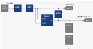
Make sure that I can use it with the following connection configurations.
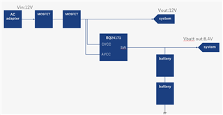
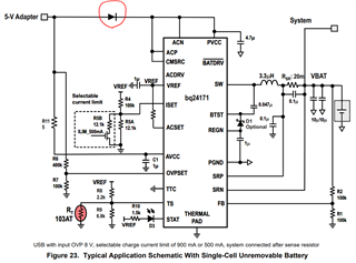
I understand that the configuration is similar to Figure23.
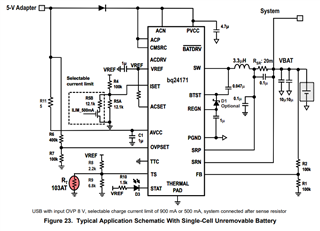
Is there any problem if I manage not to exceed the rated current of the AC adapter?

Best Regards,

Ryusuke

  • HI Ryusuke,

    Your diagram shows too different SYSTEMs, one at 12V and one at 8.4V.  If that is truly your application, I see no issues.  The d/s diagram shows system connected to battery.  

    Regards,

    Jeff

  • Hi Jeff,

    I apologize for the mistake. FET was not listed between the battery line and system line. The correct configuration is below.

    I have three questions.

    1) I think the Nch FET is controlled by the ACN and ACP pins to cut off the current in order to protect the device. Am I correct in understanding that it is latched off by controlling the FET?

    2) Is the diode circled in red in the figure below only needed in the 5 V system?

    I am thinking of using a 12 V AC/DC adapter. I am wondering whether I should use diode or FET.

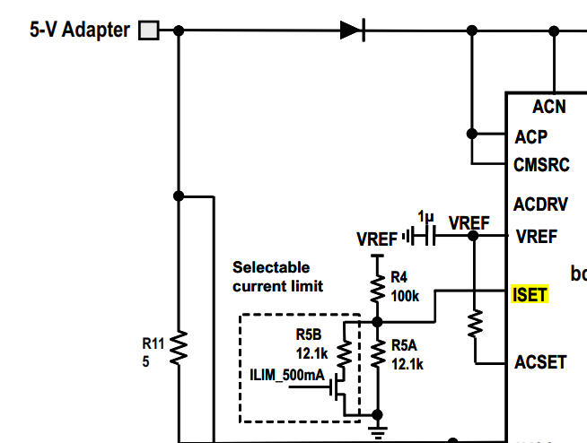
    3) Is the FET attached to the Icharge set arranged to switch between fast charging and constant charging?

    Best Regards,

    Ryusuke

  • Hello Ryusuke,

    1) I think the Nch FET is controlled by the ACN and ACP pins to cut off the current in order to protect the device. Am I correct in understanding that it is latched off by controlling the FET?

    No, The FETS are used to isolate the battery and adapter. This blocks reverse current from the battery pack to the input. The bq24171 features Dynamic Power Management (DPM) to reduce the charge current when the input power limit is reached to avoid overloading the adapter. This is set through the ACSET pin.

    2) Is the diode circled in red in the figure below only needed in the 5 V system?

    I am thinking of using a 12 V AC/DC adapter. I am wondering whether I should use diode or FET.

    They both serve the same purpose of isolating the battery and adapter. I recommend using the back-to-back FETS, because this is a higher powered application.

    3) Is the FET attached to the Icharge set arranged to switch between fast charging and constant charging?

    No, This FET is used to program a input current limit.

    Best Regards,

    Christian.

  • Hi Christian,

    Thank you for youa reply.

    1)
    I understand that it blocks reverse current.
    Is it OK to understand that the current value decreases when the input current exceeds the limit value set by the ACSET pin?

    2)
    Thank you for your answer.

    3)
    How do you limit the current? Is it OK to understand that the FET turns on and is clamped to the set current value?

    Best Regards,

    Ryusuke