This thread has been locked.

If you have a related question, please click the "Ask a related question" button in the top right corner. The newly created question will be automatically linked to this question.

BQ40Z50-R2: Min/Max RSOC for cell balancing

Part Number: BQ40Z50-R2
Other Parts Discussed in Thread: BQ40Z50, BQSTUDIO

Tool/software:

Hi,

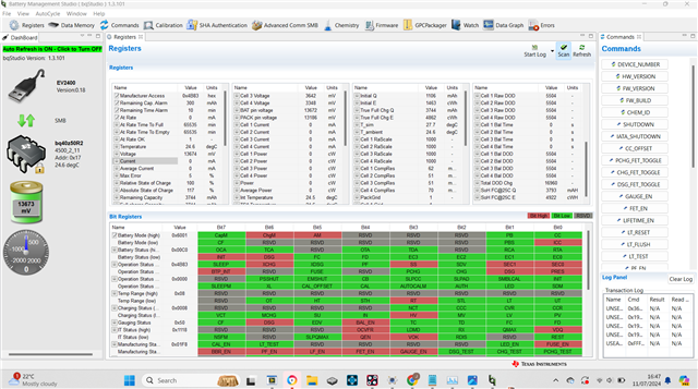
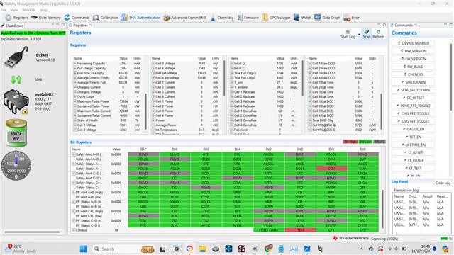
if anyone can please help me understand this cell balancing settings:

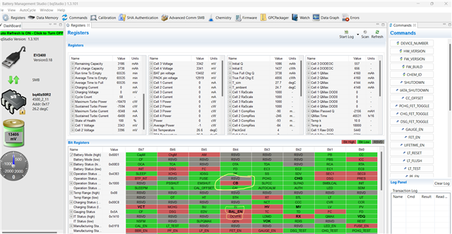
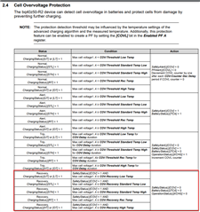
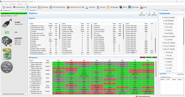
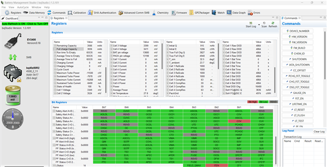
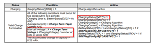
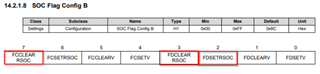
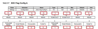
I've attached my Pack's setting which came from our supplier

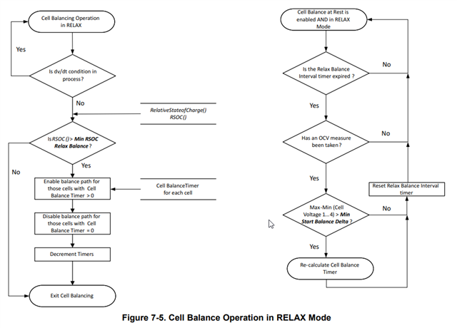
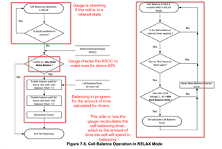
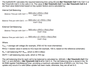
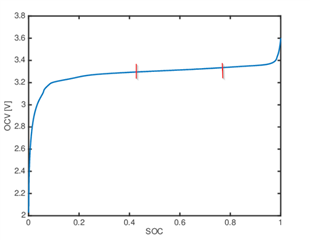
it shows minimum RSOC to trigger cell balancing

First Question: looking at the settings i don't see one for Max RSOC cell balancing 

Should this be included ???

Second question: What happens to the pack's cells outside of the Minimum and Maximum RSOC cell balancing issues 

Regards

Jonathan Kabangu

  • Hi Jonathan,

    The description for each of these registers can be found in section 14.4.12 of the bq40z50 TRM:

    https://www.ti.com/lit/pdf/sluubc1

    1) The minimum RSOC for Balancing is just a check to ensure the pack is not in a depleted state before cell balancing, so there is no need for a maximum value for this. Below is the process of checks the gauge makes during cell balancing.

    2) If the RSOC is less then the Min RSOC for Balancing, then the gauge will exit cell balancing.

    Regards,

    Anthony Baldino

  • HI Anthony,

    1a. Is there a more descriptive format of the flow chart ,so it can facilitate understanding for me as there's lots of jargon?? :)

    1b. interesting information which actually sounds right from a design perspective as the pack should not have a max RSOC for balancing!!!

    but as per our supplier they said Max RSOC for balancing is 95%

    so basically from 20%~95% that's when the balancing would occur if all condition are met 

    1c. you previously mentioned Cell balancing during relax mode ,and relax mode is defined as the time after charging or discharging that the gauge enables cell balancing

    What's cell balancing during Rest :)

    2. so below 20% Cell balancing will never occur?

    Thank you so much for bearing with me and answering so many of my questions!!!

    Regards

    Jonathan Kabangu

  • Hi Jonathan,

    1. I do not believe that there is a more descriptive flow chart, however I have added annotations to the chart above to provide more simplicity. Please let me know if more detail is needed. 

    "Cell Balancing at Rest" is the setting that needs to be set to allow the gauge to cell balance during relax. Rest is typically the period in relax where the cells are in a truly relaxed state. This is determined by the dV/dt condition being met.

    2. Correct. If the RSOC is below 20%, then the gauge will not conduct cell balancing.

    Regards,

    Anthony Baldino

  • Hi Anthony,

    1.This is brilliant!!,i will expand on each block further :)

    • is the "Dv/Dt" the different in cell voltage over time ? if not what does it define?

    • what's a typical timer for cell balancing in others words how long do they need to spend in balancing for optimum pack performance , does this depend on the calculation and setting computed during relax ?
    • "enable balance path for those cells with balance timer >0 "does each cell have each timer ? & why does this timer need to be greater than 0?

    2.

    • "has an OCV measure been taken",Why are we measuring for Over cell voltage in this stage?
    • "max-min (cell voltage 1....4)>Min start balance delta?"what does part define?

    3.Cell balance at rest can be define as the cell balancing process once pack has entered relax and it's fully taking calculations?

    Regards

    Jonathan Kabangu

  • Hi Jonathan,

    is the "Dv/Dt" the different in cell voltage over time ? if not what does it define?

    The dV/dt condition is the way the gauge determines if the cell is truly in a relaxed state. The condition is that the measured cell voltage cannot change by more then 4uV/s, to which I believe can be seen by the REST bit. I believe if this bit is set then the cell has cleared the condition.

    • what's a typical timer for cell balancing in others words how long do they need to spend in balancing for optimum pack performance , does this depend on the calculation and setting computed during relax ?
    • "enable balance path for those cells with balance timer >0 "does each cell have each timer ? & why does this timer need to be greater than 0?

    I do not believe there is a number for the typical timer since it relies on the cell voltage, however the formula to calculate this can be found below:

    The balance times are grouped for cell 1 and cell 2-4, and if that timer number is greater then 0, then the cell balancing path will open for that cell. Each cell will have an individual balancing path. The timer basically determines whether the cell needs to be balanced and for how long.

    • "has an OCV measure been taken",Why are we measuring for Over cell voltage in this stage?
    • "max-min (cell voltage 1....4)>Min start balance delta?"what does part define?

    3.Cell balance at rest can be define as the cell balancing process once pack has entered relax and it's fully taking calculations?

    OCV in this case stands for Open Current Voltage measurement, where the majority of our measurements for calculations take place. The max-min (cell voltage 1...4) > Min start balance delta is there to confirm that there is enough of a difference in the voltage between the individual cells for cell balancing to start.

    3. That is correct.

    Regards,

    Anthony Baldino

  • Hi Anthony,

    1. if Dv/Dt is <4uv/s indicates that it's a in true relaxed state, this means the pack will have be at Rest for this ,the only way you can achieve that level of small change in voltage over a second is if you're battery is not charging or discharging?
    2. not sure if they're related but OCV=Dv/Dt=<-4uV/s, this is to confirm system is in relax once again ,correct??
    3. what does the delta between the cells voltages have to be to begin balancing, what's the min and max values ?

    Regards

    Jonathan Kabangu

  • Hi Jonathan,

    1. That is correct. For this to be achieved there should not be any current being applied to the cell.

    2. They are roughly related. The OCV measurements are the measurements taken by the gauge to preform calculations to create values such as FCC, SOC, etc however the gauge will not take these measurements until the cell is in a truly relaxed state, where the dV/dt is less then 4uV/s.

    3. The delta value to begin balancing is checking the largest cell voltage in the cell stack, the lowest cell voltage in the cell stack, and subtracting them to see if the difference between the two of them is large enough to begin cell balancing. 

    Regards,

    Anthony Baldino

  • Hi Anthony,

    1. That is correct. For this to be achieved there should not be any current being applied to the cell.

    JK:no current being applied or drained from cell, in our system we're always pulling current(discharge) or applying current(charging) the pack is never at rest at one time inside the unit!!

    is this an issue long term on the performance of the pack?

    2. They are roughly related. The OCV measurements are the measurements taken by the gauge to preform calculations to create values such as FCC, SOC, etc however the gauge will not take these measurements until the cell is in a truly relaxed state, where the dV/dt is less then 4uV/s.

    JK:in the case of entering relax to enable balancing, this is only looking at the Dv/dt=4uV/s which is at rest ?

    is this 4uV/s for the pack voltage or per cell?

    Regards

    Jonathan Kabangu

  • Hi Jonathan,

    JK:no current being applied or drained from cell, in our system we're always pulling current(discharge) or applying current(charging) the pack is never at rest at one time inside the unit!!

    is this an issue long term on the performance of the pack?

    Yes, this could potentially be an issue for the long term performance of the pack. There does not need to be a relax period after every charge or discharge, however if an extended period goes by without a relax period there error can build up and there can be issues with the calculations.

    JK:in the case of entering relax to enable balancing, this is only looking at the Dv/dt=4uV/s which is at rest ?

    is this 4uV/s for the pack voltage or per cell?

    There are other factors that the gauge will look at once rest is entered, however the initial condition to enter relax is clearing the dV/dt condition. I believe this is based on the pack voltage, however I will confirm this with our team.

    Regards,

    Anthony Baldino

  • Hi Anthony,

    1.Yes, this could potentially be an issue for the long term performance of the pack. There does not need to be a relax period after every charge or discharge, however if an extended period goes by without a relax period there error can build up and there can be issues with the calculations.

    JK:our pack is most probably imbalanced due the nature of our system always discharging/charging and it never gets rest time ,this imbalance is further causing delta in cells and causing one cells to be higher than the other thus reaching max voltage before the others ,therefore pack caps <100% or it's showing improper RSOC due to not taking proper calculation for OCV?
    look example:

    2.There are other factors that the gauge will look at once rest is entered, however the initial condition to enter relax is clearing the dV/dt condition. I believe this is based on the pack voltage, however I will confirm this with our team

    Jk:please do let me know once confirmed with the team

    JK:OCV:open current voltage, this is needed to update FCC, RSOC is there a defined number or value for this setting/parameter?,without relax mode ,OCV measurement won't be taken therefore improper FCC,RSOC?

    JK:please any suggestion is welcome on how we can make our system to enter relax mode without disrupting it's operation (by taking it our the hub/device to give it rest time)

    Regards

    Jonathan Kabangu

  • Hi Jonathan,

    JK:our pack is most probably imbalanced due the nature of our system always discharging/charging and it never gets rest time ,this imbalance is further causing delta in cells and causing one cells to be higher than the other thus reaching max voltage before the others ,therefore pack caps <100% or it's showing improper RSOC due to not taking proper calculation for OCV?

    It is possible that it is showing the improper RSOC because there is no time for the OCV measurement.

    OCV:open current voltage, this is needed to update FCC, RSOC is there a defined number or value for this setting/parameter?,without relax mode ,OCV measurement won't be taken therefore improper FCC,RSOC?

    JK:please any suggestion is welcome on how we can make our system to enter relax mode without disrupting it's operation (by taking it our the hub/device to give it rest time)

    This is correct. However, there is no defined value for FCC and RSOC parameter. The main issue with there being no OCV measurement is that over time as the true FCC of the gauge changes, this will not be reflected in the measurements since there is no calculation or time to update it.

    In this system, I am not sure if there is a possible way for relax to be entered due to the constant charge or discharge, and the measurements and calculations relying on a fully relaxed cell with a period of time of no charge or discharge.

    Regards,

    Anthony Baldino

  • Hi Anthony,

    1.I had a question in regards to the bits flags being raised in BQstudio

    logically we know 1=True/ON & 0=false/OFF

    in BQstudio there's the colour RED & GREEN

    Which one represents ON and which one represents OFF?

    2. 

    What's the difference between CB&CB_EN bits?

    OCVFR=open circuit voltage flat region:what does this mean 

    SO in this case since they're RED that means it's ENABLED???

    Here's a Screenshot for ref:

    3.currently our Min RSOC for balancing is 20%

    • Can we lowered this value let's say down to 5% and what will happen if we do change this value?

    Regards

    Jonathan Kabangu

  • Hi Jonathan,

    1.I had a question in regards to the bits flags being raised in BQstudio

    logically we know 1=True/ON & 0=false/OFF

    in BQstudio there's the colour RED & GREEN

    Which one represents ON and which one represents OFF?

    Red = 1/ON

    Green = 0/OFF

    What's the difference between CB&CB_EN bits?

    OCVFR=open circuit voltage flat region:what does this mean 

    SO in this case since they're RED that means it's ENABLED???

    Here's a Screenshot for ref:

    BAL_EN means that at that moment in time, cell balancing is possible, however it does not mean whether cell balancing is actively occurring. CB means whether cell balancing is actively occurring or not (active = 1).

    The meaning of OCVFR can be found below:

    Can we lowered this value let's say down to 5% and what will happen if we do change this value?

    Min RSOC for Balancing refers to what the minimum RSOC value needs to be before balancing can occur. This value can be set to whenever you want cell balancing to begin, including 5%.

    Regards,

    Anthony Baldino

  • Hi Anthony,

    1.that paragraph does not define what's OCVFR is, i even clicked on the "SLUA372" link it does not quite expand on it,can you help out on this please :)

    in simplicity is an "open circuit voltage flat region" a good thing or bad

    2.Min RSOC for Balancing refers to what the minimum RSOC value needs to be before balancing can occur. This value can be set to whenever you want cell balancing to begin, including 5%.

    JK:our battery vendor told us the reason this is at 20% is because cell balancing process drains the battery capacity so setting it at 20% was a safe bet rather than 10% or 5% ,is this accurate?

    Regards

    Jonathan Kabangu

  • Hi Jonathan,

    1.that paragraph does not define what's OCVFR is, i even clicked on the "SLUA372" link it does not quite expand on it,can you help out on this please :)

    in simplicity is an "open circuit voltage flat region" a good thing or bad

    Being within the OCVFR is not a good thing, since when the gauge begins to take OCV measurements to update the Qmax parameter of the gauge, these measurements and calculations will be invalidated if the measured voltage is within this region. Where this region is based on the chemID being used. When the cell is at rest, this region should be avoided.

    our battery vendor told us the reason this is at 20% is because cell balancing process drains the battery capacity so setting it at 20% was a safe bet rather than 10% or 5% ,is this accurate?

    This is correct. Having the parameter at 20% can protect the individual cells from becoming too low.

    Regards,

    Anthony Baldino

  • Hi Anthony,

    1.Being within the OCVFR is not a good thing, since when the gauge begins to take OCV measurements to update the Qmax parameter of the gauge, these measurements and calculations will be invalidated if the measured voltage is within this region. Where this region is based on the chemID being used. When the cell is at rest, this region should be avoided.

    JK:how do we avoid being in this flat region?

    is there any numerical value to watch out for that can indicate if we're in this region?


    2.

    in the screenshot above the CB,CB_EN & REST flags are all 1/ON

    2A. how's cell balancing possible whilst charging 

    2B. When Pack is charging this is not longer in rest ? so how come the REST flag is raised 

    Regards

    Jonathan Kabangu

  • Hello Jonathan,

    Anthony will be out of town for a while, but I can continue to support you.

    JK:how do we avoid being in this flat region?

    To help answer this, can you tell me more about the typical application you will be using. Maybe even sharing a load profile that might be typical for your system.

    is there any numerical value to watch out for that can indicate if we're in this region?

    This depends greatly on the specific battery and chemistry. 

    2A. how's cell balancing possible whilst charging 

    Please read this documentation to learn more about this: https://www.ti.com/lit/an/slva155/slva155.pdf

    2B. When Pack is charging this is not longer in rest ? so how come the REST flag is raised 

    Can you send me a log file of this occurring? Can you also send me the gg file for the gauge?

    Regards,

    Nick Richards

  • HI Nick,

    1.NR:To help answer this, can you tell me more about the typical application you will be using. Maybe even sharing a load profile that might be typical for your system.

    • JK:in terms of application our device lies inside a hub and delivers power to an internal security device inside a car and pulls a max current of 400~450mA
    • there's also a sleep mode of about 20~30mA until it detects an event then it goes up 450mA
    • I will try to get a load profile for you 

    2.if you can get information and details on flat region values for Lifepo cells that will be appreciated

    3.another issue occurred whilst i tried getting the log for you ,the pack stopped charging and the pack enabled "COV" and stopped charging at 94%

    i'm guessing cell 3 hit COV ,i'd like to understand the root cause it was simply in charge then this happened

    furthermore how did this happen as CB & CB_EN is enabled meaning it's balancing cells but the

    log file:

    NL-02.log

    gg file:

    nl02gg.gg.csv

    Regards

    Jonathan Kabangu

  • Hello Jonathan,

    • there's also a sleep mode of about 20~30mA until it detects an event then it goes up 450mA
    • I will try to get a load profile for you 

    I took a look at your gg file and I think the dsg current threshold should be set lower to account for the sleep mode current of between 20-30mA. Right now the Dsg current threshold is set to 100mA and I think it will be best if that is set below 20mA. So maybe around 15mA. 

    if you can get information and details on flat region values for Lifepo cells that will be appreciated

    I can not share specific voltage values of the flat region however I can share some knowledge in terms of estimating the flat region. LFP chemistry is much more difficult because it has a larger flat region compared to other chemistries. 

    This is an example graph of the discharge profile for an LFP battery and the red lines is what I would consider to be an approximation of the flat region. 

    The gauge implements passive cell balancing and it takes a while for the cells to become balanced since it uses very small current to balance the cells. If you want the cells to balance faster, then you will need to implement an active cell balancing circuit.

    Regards,

    Nick Richards

  • Hi Nick/Anthony,

    sorry for the delayed response ,been out of town for a few days

    1. as for the CHG/DSCH current thresholds ,are these the points to which charging is triggered ?, e.g when charging input is applied to pack as soon as as it sees current let's say 15mA for a certain amount then Pack will enter charge mode?,similarly for discharge if it sees 15mA for a certain period then it will enter discharging mode ?
    2. how do we better control the Flat region so our pack never enters this section whilst taking measurements?
    3. when one of the cells hit COV does it recover itself ?
    4. when COV occurs is this due to imbalance in cells since one of the cells has it's maximum first ?
    5. what's the difference between Passive & active balancing in layman's term

    hope to hear from you soon

    Regards

    Jonathan Kabangu

  • Hi Jonathan,

    as for the CHG/DSCH current thresholds ,are these the points to which charging is triggered ?, e.g when charging input is applied to pack as soon as as it sees current let's say 15mA for a certain amount then Pack will enter charge mode?,similarly for discharge if it sees 15mA for a certain period then it will enter discharging mode ?

    When either the CHG or DSG Threshold is passed, the gauge will enter the respective mode for the current being seen. This is measured across the sense resistor over a 1s period, meaning the average current over the one second period must break the threshold. The gauge will automatically enter the respective mode after this is seen.

    how do we better control the Flat region so our pack never enters this section whilst taking measurements?

    The flat region is not something that can be altered, since it is defined by the chemID being used with the gauge. 

    when one of the cells hit COV does it recover itself ?

    If COV is triggered, the gauge will recover if the conditions below are met:

    what's the difference between Passive & active balancing in layman's term

    Passive cell balancing dissipates charge throughout the charge cycle, while active cell balancing redistributes the charge during the charge cycle.

    Regards,

    Anthony Baldino

  • Hi Anthony,

    it's set at 3750mV ,the recovery setting is implemented at 3500mV

    Question:See screenshot:

    gg file:01GU.gg.csv

    gg file:006k.gg.csv

    :Why's the COV triggering at 100%

    • i heard active balancing is much better and faster than passive ?

    Regards

    Jonathan Kabangu

  • Hi Jonathan,

    I believe the COV protection is not clearing due to the Cell 3 voltage being higher then the recovery threshold. Also, I cannot pin point where the COV protection was triggered without a log file, however there could of been a moment where the COV protection threshold was passed by one of the cells.

    I believe that active balancing is more effective then passive.

    Regards,

    Anthony Baldino

  • Hi Anthony,

    if you look at the screenshot ,this flag seems to raising after pack has reached 100%,any reason why?

    i will provide logs for this pack tomorrow so we can deep dive it further

    i will look into active balancing method and it's advantages 

    Regards

    Jonathan Kabangu

  • Hi Jonathan,

    if you look at the screenshot ,this flag seems to raising after pack has reached 100%,any reason why?

    I believe the log file will give us better insight into why this is potentially occurring within the gauge.

    Regards,

    Anthony Baldino

  • Hi Anthony,

    I've been trying to reproduce cause the same pack no longer shows this COV bit

    from the Screenshot it looks cell 3 went above the COV Theshold

    My question:

    once pack has reached 100% ,no cells should be topped up further i'm interested as to why this reached 3750mV> at 100% or after

    Regards

    Jonathan Kabangu

  • Hi Jonathan,

    When Valid Charge Termination is reached, the gauge's charging algorithm will change to the maintenance charge, which should keep the voltage of the device at the same place, but it will not stop charge all together. If possible, can you see what the charge current was once 100% was reached?

    Regards,

    Anthony Baldino

  • Hi Anthony,

    somehow i forgot to attach the screenshots and logs so we can analyse this 

    logs:0037 (1).log

    Current

    AvgCurr

    MaxErr

    RSOC

    ASOC

    RemCap

    FullChgCap

    RunTimeEmty

    AvgTimeEmty

    AvgTimeFull

    ChgCurr

    ChgVolt

    BattStat

    CycleCnt

    MaxTurboPwr

    SusTurboPwr

    MaxTurboCurr

    SusTurboCurr

    SoH

    OpStatA

    OpStatB

    TempRange

    ChgStat

    GaugeStat

    ITStat

    MfgStat

    SafetyAlertAB

    SafetyStatAB

    SafetyAlertCD

    SafetyStatCD

    PFAlertAB

    PFStatAB

    PFAlertCD

    PFStatCD

    CellVolt1

    CellVolt2

    CellVolt3

    CellVolt4

    0

    0

    1

    100

    120

    3837

    3837

    65535

    65535

    65535

    900

    14000

    C0

    2

    -12270

    -7772

    -10955

    -6400

    100

    307

    1000

    8

    8

    50

    14

    1B8

    0

    0

    0

    0

    0

    0

    0

    0

    3516

    3414

    3420

    3355

    0

    0

    1

    100

    120

    3837

    3837

    65535

    65535

    65535

    900

    14000

    C0

    2

    -12270

    -7772

    -10955

    -6400

    100

    307

    1000

    8

    8

    50

    14

    1B8

    0

    0

    0

    0

    0

    0

    0

    0

    3515

    3415

    3421

    3354

    0

    0

    1

    100

    120

    3837

    3837

    65535

    65535

    65535

    900

    14000

    C0

    2

    -12270

    -7772

    -10955

    -6400

    100

    307

    1000

    8

    8

    10

    14

    1B8

    0

    0

    0

    0

    0

    0

    0

    0

    3540

    3434

    3439

    3378

    914

    252

    1

    100

    120

    3837

    3837

    65535

    65535

    0

    900

    14000

    80

    2

    -12275

    -7772

    -10960

    -6400

    100

    387

    1002

    8

    8

    10

    14

    1B8

    0

    0

    0

    0

    0

    0

    0

    0

    3606

    3454

    3459

    3385

    909

    410

    1

    100

    120

    3837

    3837

    65535

    65535

    0

    900

    14000

    80

    2

    -12275

    -7772

    -10960

    -6400

    100

    387

    1002

    8

    8

    10

    14

    1B8

    0

    0

    0

    0

    0

    0

    0

    0

    3675

    3469

    3475

    3389

    857

    523

    1

    100

    120

    3837

    3837

    65535

    65535

    0

    900

    14000

    80

    2

    -12275

    -7772

    -10960

    -6400

    100

    387

    1002

    8

    8

    10

    14

    1B8

    0

    0

    0

    0

    0

    0

    0

    0

    3744

    3482

    3489

    3391

    892

    609

    1

    100

    120

    3837

    3837

    65535

    65535

    0

    0

    0

    80

    2

    -12270

    -7772

    -10955

    -6400

    100

    4B83

    1002

    8

    8

    10

    14

    1B8

    0

    2

    0

    0

    0

    0

    0

    0

    3789

    3479

    3486

    3372

    -10

    -9

    1

    100

    120

    3837

    3837

    23022

    25580

    65535

    0

    0

    C0

    2

    -12270

    -7772

    -10955

    -6400

    100

    4B83

    1000

    8

    8

    50

    1014

    1B8

    0

    2

    0

    0

    0

    0

    0

    0

    3771

    3458

    3466

    3368

    -9

    -9

    1

    100

    120

    3837

    3837

    25580

    25580

    65535

    0

    0

    C0

    2

    -12270

    -7772

    -10955

    -6400

    100

    4B83

    1000

    8

    8

    50

    1014

    1B8

    0

    2

    0

    0

    0

    0

    0

    0

    3760

    3451

    3459

    3367

    -8

    -9

    1

    100

    120

    3837

    3837

    28778

    25580

    65535

    0

    0

    C0

    2

    -12270

    -7772

    -10955

    -6400

    100

    4B83

    1000

    8

    8

    50

    1014

    1B8

    0

    2

    0

    0

    0

    0

    0

    0

    3751

    3447

    3454

    3365

    if you look at the logs and values above the current is at about 892mA at 100%,this then pushed then cells to go above COV, this tells me that the charge termination did not kick in to reject charging once 100% was reached any reason why 

    Regards

    Jonathan Kabangu

  • Hi Jonathan,

    I believe that since for valid charge termination needs to be met for 2 consecutive 40 second periods, the sudden jump in voltage from 13700 to 14000+ is causing the COV protection to go off since the timing was not met to meet valid charge termination and the voltage went right past it.

    Regards,

    Anthony Baldino

  • Hi Anthony,

    Charge term voltage :100mV

    what does this mean and how do i watch out for it if it's met or not?

    Regards

    Jonathan Kabangu

  • Hi Jonathan,

    The charge term voltage is used to meet the condition below, where it is added to the maximum cell voltage then compared to the charging voltage. If this condition along with the other conditions below are met for 2 consecutive 40 second periods, then the [VCT] bit will become set.

    Regards,

    Anthony Baldino

  • Hi Anthony,

    Just to confirm ,is the charge term voltage something we can see in the BQstudio registers in real time like the avg current, remaining capacity ?

    Regards

    Jonathan Kabangu

  • Hi Jonathan,

    The Charge Term Voltage is a settable parameter that can be found in the Data Memory section of bqStudio. This parameter is static and should not move during the functioning time of the gauge.

    Regards,

    Anthony Baldino

  • Hi Anthony,

    can you help out with this please,FC & TC are not being set despite our Pack meeting the conditions(3500mv,100%)

    i've attached logs,screenshot and gg file of the pack

    6332.01NL.log

    3460

    3621

    3589

    3619

    3460

    3621

    3588

    3619

    3460

    3621

    3589

    3618

    3461

    3621

    3589

    3619

    3461

    3621

    3589

    3619

    3461

    3622

    3589

    3618

    2112.01NL.gg.csv

    Regards

    Jonathan Kabangu

  • Hi Jonathan,

    In your SOC Flag Config A and SOC Flag Config B, you have FC and TC to set upon valid charge termination. These parameters can be changed in the registers below:

    Regards,

    Anthony Baldino

  • Hi Anthony,

    How were you able to figure that information out?

    cause all i can see in the gg file is this 

    can you breakdown what the hex codes mean please

    Regard

    Jonathan Kabangu

  • Hi Jonathan,

    To understand the bits within the register, convert the value from hex to binary:

    8C -> 10001100

    Regards,

    Anthony Baldino

  • Hi Anthony,

    I will play about with these settings and update you 

    Regards

    Jonathan Kabangu

  • Hi Jonathan,

    Understood, please let us know if there is any improvement in performance.

    Regards,

    Anthony Baldino

  • Hi Anthony,

    Question 1: For FC or TC to be set do we need to meet ALL conditions set in the gg file or if we meet one of them the bit will set?

    example for FC:

    for this to be TRUE(FC=1) ,does voltages of all cells have to be above 3.5V AND RSOC @ 100% or if we meet one of the two conditions then this will be TRUE

    Example for TC:

    for this to be TRUE(TC=1) ,does voltages of all cells have to be above 3.5V AND RSOC @ 100% or if we meet one of the two conditions then this will be TRUE

    Question 2:

    1. Although Reached 100% ,VCT ,FC or TC is NOT SET?
    2. do all cells have meet the FC,FC threshold at 3.5V for it to be set to 1?
    3. does COV play a part here on not seeing these bits turning ON?
    4. the gauge seems to be balancing by the indication of CB,CB_EN flags but the DSG flag is also ON which indicates the system is discharging ,and from my understanding Cell balancing does not occur during discharge so how is this possible?

    Regards

    Jonathan Kabangu

  • Hi Jonathan,

    Question 1: For FC or TC to be set do we need to meet ALL conditions set in the gg file or if we meet one of them the bit will set?

    example for FC:

    for this to be TRUE(FC=1) ,does voltages of all cells have to be above 3.5V AND RSOC @ 100% or if we meet one of the two conditions then this will be TRUE

    Example for TC:

    for this to be TRUE(TC=1) ,does voltages of all cells have to be above 3.5V AND RSOC @ 100% or if we meet one of the two conditions then this will be TRUE

    I believe that meeting just one of the thresholds should set the FC or TC bit.

    Although Reached 100% ,VCT ,FC or TC is NOT SET?

    I would need a log file to look deeper into what is occurring here,

    do all cells have meet the FC,FC threshold at 3.5V for it to be set to 1?

    Just the Maximum Cell Voltage from the stack has to meet the threshold for the FC bit to be set.

    does COV play a part here on not seeing these bits turning ON?

    Potentially, I would need to see the log file to understand what is going on here deeper. Looking at the TRM, the COV protection only alters the [TCA] bit out of the ones above.

    the gauge seems to be balancing by the indication of CB,CB_EN flags but the DSG flag is also ON which indicates the system is discharging ,and from my understanding Cell balancing does not occur during discharge so how is this possible?

    The DSG bit reflects when the gauge is in discharge or relax. Cell Balancing can occur in relax mode.

    Regards,

    Anthony Baldino

  • Hi Anthony,

    You mentioned "In your SOC Flag Config A and SOC Flag Config B, you have FC and TC to set upon valid charge termination. These parameters can be changed in the registers below:"

    JK: Does this mean that the TC and FC flags are tied to VCT, in other words for TC and FC it will only be set if VCT is TRUE, is this correct?

    JK:is this the setting that's implemented on our gauge?

    JK:not sure if you've already defined this but was wondering how were you able to figure out that our setting is TC & FC were TRUE upon VCT=1,

    all the GG file says is:

    SOC flag Config A:0c8c

    SOC flag Config B:8c

    JK: Wanted to Breakdown the conditions for VCT further, correct me if my statement is wrong!!

    All of the following conditions must occur for

    two consecutive 40-s periods:

    Charging (that is, BatteryStatus[DSG] = 0) :Battery has to be in charge mode

    AND

    AverageCurrent() < Charge Term Taper: The average current that is the charge current has to be less than the termination current 

    Current AND

    Max cell voltage1..4 + Charge Term

    Voltage ≥ ChargingVoltage() / number of: the voltages of the cells combined plus the termination voltage has to be greater the charging voltage divided by the number of cells in series 

    cells in series AND

    The accumulated change in capacity >: i'm not too sure about this one ,can you explain it please?

    0.25 mAh

    Regards

    Jonathan Kabangu

  • Hi Jonathan,

    JK: Does this mean that the TC and FC flags are tied to VCT, in other words for TC and FC it will only be set if VCT is TRUE, is this correct?

    If [TCsetVCT] and [FCsetVCT] are set in the SOC Flag Config A, then this will rely on VCT being true.

    not sure if you've already defined this but was wondering how were you able to figure out that our setting is TC & FC were TRUE upon VCT=1,

    The gg file tells the register value in a hexadecimal value. To find the settings, convert the value to binary and compare with the mapping for the register in the TRM.

    0C8C -> 1100 1000 1100

    The accumulated change in capacity >: i'm not too sure about this one ,can you explain it please?

    Your understanding is correct. The accumulated change in capacity means that the amount of passed charge within the period cannot exceed 0.25mAh. This means that the current needs to be low enough to not break this condition.

    Regards,

    Anthony Baldino

  • Hi Anthony,

    "The gg file tells the register value in a hexadecimal value. To find the settings, convert the value to binary and compare with the mapping for the register in the TRM."

    0C8C -> 1100 1000 1100

    JK: What is the TRM, so i can compare those binary values against it ???

    Regards

    Jonathan Kabangu

  • Hi Jonathan,

    The TRM is the bit mapping of the register. They can be compared like below:

    0C8C -> 1100 1000 1100

    The red box correlates to a 1, meaning that bit is set.

    Regards,

    Anthony Baldino

  • Hi Anthony,

    i get that part but i'm still a little bit confused on how 0c8c--> 1100 1000 1100 corresponds to TCSETVCT,FCSETVCT etc...

    it does not show on the Datasheet document how that hexcode translates to those bits 

    TCSETVCT=11

    FCSETVCT=10

    TCCLEARRSOC=7

    TDCLEARRSOC=3

    TDSETRSOC=2

    hope you do not mind breaking this down further Slight smile

    Regards

    Jonathan Kabangu

  • Hi Jonathan,

    Please let me know if this helps:

    The Technical Reference Manual can be found here: https://www.ti.com/lit/pdf/sluubk0 

    The bits directly correlate to the binary translation of the hex value.

    Regards,

    Anthony Baldino

  • Hi Anthony,

    Just back on this topic 

    For VCT condition to be met i believe there's several condition that needs to be met ,

    as seen here

    • Do we know how long in practice this may take to set VCT?
    • For our Pack the LED goes solid at 100% to indicate 100% but then the LED stays solid until the VCT conditions are met then it goes OFF,in other words the charge termination in our pack is linked to our LED,that's why i asked how long can this VCT condition take so it can be set?

    Regards

    Jonathan Kabangu

  • Hi Jonathan,

    Do we know how long in practice this may take to set VCT?

    At minimum, it will take 80 seconds due to two different 40s periods. It could take longer if any of the conditions are not met during this time.

    For our Pack the LED goes solid at 100% to indicate 100% but then the LED stays solid until the VCT conditions are met then it goes OFF,in other words the charge termination in our pack is linked to our LED,that's why i asked how long can this VCT condition take so it can be set?

    Understood, is it being seen that this process is taking an extended amount of time to complete?

    Regards,

    Anthony

  • HI Anthony,

    80 seconds minimum as per the documentation ! but this is not the case for our pack, did testing around this the longest it took was 20 minutes and the quickest time was 2 minutes ,any reason why this is happening 

    i'll share with you the test report

    i'll also share with you the log for the for pack that took the 

    FE002FJ00263240005Z-01:this pack met the condition the fastest

    005Z-01.log

    FE002FJ002632400AN-01:this pack took the longest:

    00AN-01.log

    FE002FJ002634301NL-02:this took 4 minutes

    01NL-01.log

    FE002FJ00263170005-01:this pack took 10 minutes

    0050-01.log

    Can you have a look at the logs and please help me understand why they all have different timing for VCT Setting 

    Regards

    Jonathan Kabangu