UCC28061-Q1: Automotive Qualified Analog PFC Controller

Part Number: UCC28061-Q1
Other Parts Discussed in Thread: UCC28070-Q1, UCC2818A-Q1, UCC28063, UCC28061, PMP11282, UCC28060, UCC28180, UCC2818, UCC2818A

Tool/software:

Hi TI Team,

Can you suggest an automotive analog PFC controller for the following requirements?

1. Input voltage range: 90VAC to 135VAC

2. Peak output power: 300W

3. Rated output power: 200W

4. Standby load power: 10W

5. Standby power factor: 0.85 lagging

6. Rated and peak power factor: 0.95

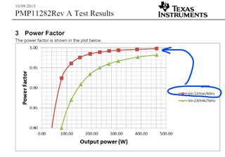
In this application, the system will mostly operate under standby load power, the rated and peak power load will operate for a  short duration of less than a minute of time. I found the UCC28061-Q1 from an online source, but I would appreciate any suggestions for better ICs if available. If not, could you share the power factor curve for the UCC28061-Q1 EVM from no load to full load? This information will be helpful for selecting this IC for my design.

Best Regards,

Aravind S.

  • Hello Aravind, 

    Thank you for your interest in the UCC28061-Q1 interleaving TM-PFC controller. 

    From TI's selection list I find that UCC28061-Q1, UCC28070-Q1, and UCC2818A-Q1 are the automotive-rated PFC controllers available from TI.  
    The -061 is interleaving Transition Mode (TM), while the -070 is interleaving CCM, and the -18A is single-phase CCM. 

    The -061 controller cost is lowest, but uses two boost stages in parallel to spread the losses out and allow for low-profile packaging.  Component count and cost may be high.
    The -070 cost is highest, and interleaves for the same reason, but is more suited to much higher power conversion. 
    The -18A cost is nearly as high, but is single-phase so number of components and their costs can be lower. 

    Thermal design will depend on the ratio of high power time to standby time.  The time interval for peak power will determine if the PFC must be designed for 300W or can be rated for 200W (with 300W peak coming from stored charge in the output capacitor).  These timings have not been provided. 

    Your requirements are achievable except #5.  Standby PF will be leading, not lagging, and it may be < 0.85 depending on how much X-capacitance is used in the line filter. 
    I do not have a PF vs. load curve for the UCC28061 EVM, however, I have found this curve from the PMP11282 460-W reference design using a similar UCC28063 controller.

    As can be seen, PF falls off below 0.85 at ~50W, which is about 11% of rated load. 
    In your design, 10W is only 5% of 200W and 3.3% of 300W, so PF might be much lower than 0.85 unless the line filter is designed to use very little X-capacitance.
    Light-load distortion will also factor into lower PF.

    Regards,
    Ulrich

  • Hi Team,

    During light load conditions how to enable the burst mode operation.

    Regards,

    Aravind S.

  • Hello Aravind,

    That "Burst Operation" signal in the UCC28061-Q1 (and UCC28061) datasheet is a mistake.  It should not be there. 
    The block diagram is in error.  It was carried forward from the UCC28060 datasheet and modified (but apparently not completely) for the -061 datasheet.  

    There is no Burst function in the UCC28061 device.  It is present in the UCC28060, but removed from the -061. See this comparison table:
    UCC28060 vs UCC28061.pdf

    Regards,
    Ulrich

  • Hello Ulrich,

    Regarding the component selection, we are facing a critical challenge in Total Harmonic Distortion (THD) and Power Factor (PF). So far, I am convinced with the UCC28061-Q1 as it works in Interleaved TM mode and during light load conditions, it operates in single phase CRM or DCM mode. Therefore, we need the THD and PF information along with the individual harmonics level for the following conditions on UCC28061-Q1 EVM:

    Input Power (35VA, 50VA, 75VA, 100VA, 150VA, 200VA, 250VA, 265VA) across the input frequency range of 350, 500, 700, 800Hz.

    Can you suggest any automotive-grade solution with less THD and better PF at light load conditions like 30 to 35VA of input power, with a maximum load of 260VA?

    Regards,

    Aravind S.

  • Hello Aravind, 

    The fact that you application is for Avionics PFC is new information. 
    Line frequencies from 350Hz to 800Hz reduce PF especially at light loads mainly due to high displacement current in the EMI filter X-caps. 
    This current is 90-degrees out of phase with the line voltage and often exceeds the actual in-phase (resistive) load current. 

    THDi still plays a roll in PF, but not as much as cosθ.  

    We are not in a position to take measurements on the EVM and provide you with data.  That is not the function of this forum. 
    In any case, data at frequencies > 60Hz are invalid since the EVM is not designed to support Avionics.   

    Line filter capacitance affects the cosθ factor of PF independently of any PFC controller.
    Of the limited automotive-qualified controllers currently available from TI, the UCC28061-Q1 has an advantage of being able to shed a phase under light-load conditions to improve (not only efficiency, but) THDi during such conditions. 

    Regards,
    Ulrich 

  • Hi Ulrich,

    What is the difference between UCC2818A-Q1 and UCC28180? One of our reference designs uses UCC28180 and meets the current Total Harmonic Distortion (THD) criteria, but it is not automotive qualified. If I use UCC2818A-Q1 in my design, will I achieve the same current distortion curve?

    Regards,

    Aravind S.

  • Hi Aravind, 

    The UCC28180 is an 8-pin CCM-PFC controller which works by leading-edge PWM modulation to have the switching cycle off duty cycle D' follow the Vin over Vout ratio over the line cycle (which shapes the current).  The control is optimized for "universal line" operation (85~264Vrms) and ~400V output with little tolerance for deviations from this typical application.  It does not include input voltage feedforward.  It has a slightly higher frequency range than the -18A.

    The UCC2818A-Q1 is an older 16-pin CCM-PFC controller which uses the traditional 3-input multiplier method for shaping input current. It also uses leading-edge PWM and includes input voltage feed-forward.  Having more pins allows more flexibility in adapting (statically and dynamically) to applications.  I think this device can probably deliver better THDi performance than the UCC28180, especially at lighter loads.  How much better I can't guess.    
    But being an older process technology in a larger package makes it more expensive than the -180. 

    Both devices are single-phase boost, so do not have any phase-shedding option for light-load efficiency improvement.  Neither have a burst mode feature, but I'm thinking it might be easier to implement one externally with the -18A than with the -180.  

    Regards,
    Ulrich

  • Hi Ulrich,

    Please let me know the changes between the UCC2818 and UCC2818A-Q1 parts. The max. negative junction temperature of the Q1 part is (-40C) and the industrial-qualified part is (-55C). Kindly let me know which mode of operation the device will perform during light load efficiency.

    Regards,

    Aravind S.

  • Hi Avarind, 

    The UCC2818A-Q1 is an automotive-qualified version of the UCC2818A.  

    Please see this App-note about the differences between UCC2818A and UCC2818.  By extension, the app-note will also apply to -2818A-Q1 and -2818.
    Differences between UCC2817A-18A-19A and UCC2817-18-19 slua294.pdf
    Basically, only the effective resistances of the pull-up and pull-down MOSFETs in the gate-drive circuit are different (higher in -2818A-Q1).

    All three versions of the UCC2818x device are characterized, and parameters are guaranteed, to -40C.  
    -55C is the absolute maximum limit on Tj for UCC2818 and UCC2818A, but parameters are not guaranteed for Tj < -40C. 
    UCC2818A-Q1 has been rerated for an Abs Max lower limit on Tj of -40C and well as being characterized to that temperature. 
    Basically, the effective lower Tj limit for all three are the same, at -40C.

    Regards,
    Ulrich  

  • Hi Ulrich,

    Please let me which mode of operation the device will perform during light load efficiency.

    Regards,

    Aravind S.

  • Hi Avarind, 

    Sorry, I missed your last question in my previous reply. 

    The UCC2818x does not have any special mode for light load.  It will continue to operate as a fixed-frequency  CCM-PFC using average current-mode control.  At some light load level, inductor current may become discontinuous, so THDi may increase, but this controller will not change its basic cycle-by-cycle operation. 

    Ast some very light load level, the VAOUT voltage may fall to less than the 0.33V "zero-power" threshold and the zero-power comparator will block gate-drive pulses (at DRVOUT) until VAOUT rises above 0.33V again (there is no hysteresis specified.)   Then operation may appear to resemble a burst mode, but it is mainly a random burst result, not a pre-programmed pattern.  

    Regards,
    Ulrich

  • Hi Ulrich,

    I’m not getting the PSpice file for the UCC2818A-Q1 device. If the library part is available, please share it with me. Otherwise, share the PSpice part with a similar working principle because I want to do a simulation to verify the inductor ripple and for further analysis. So, please share this part or any similar one to predict the same result.

    Regards,

    Aravind S.

  • Hello Aravind, 

    Unfortunately, the UCC2818A-Q1 (or any of its family parts) does not have a PSpice file. 
    This device works as a fixed-frequency CCM boost-PFC controller.  The closest part with a similar working principle is the UCC28180 controller.

    The UCC28180 does have a PSpice model, but this model is an Average model, not a transient model.  It only generates average inductor current, not cycle-by cycle ripple current, so it is not suitable for your needs. 

    I suggest that the UCC2818A-Q1 block diagram consists of simple analog blocks which should be able to be modeled in PSPICE with relatively straight-forward construction using ideal components and datasheet parameter values.  I understand that this is extra work that you didn't expect to have to do, but I have no other alternative to offer. 

    Regards,
    Ulrich

  • Hello Ulrich,

    In the voltage feedforward (VFF) pin, the potential divider is missing, right?

    In the design, 90Vrms to 135Vrms is the nominal rated voltage, but abnormal surge voltages like 160Vrms and 180Vrms will occur for less than or equal to 250ms. During these voltage transients, I plan to disable the PFC controller by pulling the enable pin to ground. The input voltage will be continuously monitored, and if it is less than 80Vrms or greater than 140Vrms, the disable operation will be triggered.

    However, I have a doubt about the IAC and VFF pins. For what maximum input voltage should the pins be designed: 140Vrms or 180Vrms?

    If I design for 140Vrms, the IAC and VFF pins might get damaged, right? So, can I design for 180Vrms so that if my input voltage crosses 140Vrms, I can disable the controller? Confirm whether this method will work out or not. If this is the suggested method, will I face any impact on performance, like THD and PF? Otherwise, suggest the best method for this.

    Regards,

    Aravind S.

  • Hello Aravind, 

    The VFF pin of the UCC2818A-Q1 ( and others in this family) do not use a potential divider.  The VFF voltage is developed from 1/2 of IAC current mirrored into the VFF resistor and filtered with the VFF capacitor.  The VFF and IAC pin functions are discussed in the datasheet. 

    I suggest to design your PFC and program IAC at 135Vac max for best THDi in the normal range of operation.  At higher input voltages, IAC will exceed the recommend maximum of 500uA (there is a typo in the datasheet where it says "500mA".  It should be 500uA.) but that merely pushes the multiplier out of its linear range.  The MULTOUT current will begin to saturate and THDi will go up, but it won't harm the device. 
    Absolute Maximum current into IAC is rated at 10mA. 

    I think that your plan to detect Vac > 140Vrms to disable the PFC should work okay.  

    At this point, I would like to conclude this thread as it has strayed far from the original question involving UCC28061-Q1. 
    I should have done this actually much earlier.  
    If you need further help with the UCC2818A-Q1 or some other device, please post a new E2E thread. 

    Regards,
    Ulrich