Other Parts Discussed in Thread: TPS54821
Tool/software:
Hello,

I would like to use a TPS56837RPAR for our new design.
V in is 15V, V out between 3.5V to 12.5V, adjustable using a DC voltage between 0 (12.5V) and 3V (3.3V)
Required maximum current out 5/6A
I've made de board, trying to follow the PCB layout given by the DEV. KIT (4 layers).
Unfortunately, I am having problems with currents over 2.5A (3.3R load), the efficiency drops dramatically from about 80% down to 60% !
Lots of oscillations (30Khz), at 6.5V the buck sound (literally... inductor noise) unstable ?
I don't really understand the relation-ship in the control loop, with the output capacitors (I need a very low noise), load impedance and feedback resistors (+ small cap) ?
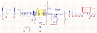
I've attached the my circuit; for your review, if possible please.
I use a 2.2uH, I dc 10A, I sat 15A. Fo 800Khz
thank you for your support
Best regards