This thread has been locked.

If you have a related question, please click the "Ask a related question" button in the top right corner. The newly created question will be automatically linked to this question.

BQ40Z80: BMS discharging the battery Pack

Part Number: BQ40Z80

Tool/software:

Dear Sir,

We have designed a BMS system with a 6s configuration with COV parameters set to 4.2V/cell and CUV set to 2.5V/cell. We have installed a BMS inside the battery pack and flashed our BMS as ,it was programmed successfully. After programming, it was showing successfully 25.20V but then I kept BMS aside for 2 days hoping it was working fine.Later, when I saw BMS it was not showing voltage and it was showing communication error. After that, I opened the battery pack and check BMS board was fine but my individual cell voltage dropped to 5mV and some cells to 1V. I don't know how these issue has happen, and what will be the possible cause of these issues are. Is there any parameters changes in srec file required to overcome these issue? or What causing these battery to get deeply discharged?

Waiting for your reply,
Shubham

  • Hi Shubham,

    In the BMS system, is there anything connected to the PACK pin of the gauge that could have drawn current from the cells? If there was a current less then the DSG Current Threshold of the gauge, the cells could have potentially been discharging. If you send the .gg file, we can look into the protection settings as well.

    Regards,

    Anthony Baldino

  • In the BMS system, is there anything connected to the PACK pin of the gauge that could have drawn current from the cells?

    There is no connection at pack pin when BMS is idle, Can passive cell balancing in BMS could cause these issue?
    I have attached gg.csv flie, please have a look at it and let me know if any is correction needed. Sir, we have used press pin functionality in our design so whenever BMS is connected to external system then only it will supply voltage to the load.

    7 june.gg.csv

    Waiting for your reply,
    Thanks & Regards,
    Shubham 

  • Hi Shubham,

    Thank you for sending the .gg file, we will take a look into it.

    When there is no connection being made to the PACK pin, is it possible to measure the current on it to ensure there is nothing being pulled at the time? Since this is a custom PCB as well, we can look into the schematic and layout to confirm if you would like.

    Regards,

    Anthony Baldino

  • Dear Sir,

    Based on the previous discussion, today also we have faced the same related  problem. Actually, we had charged 2 battery pack fully up to 24.75 and kept aside for 10 days. Then, after 10 days, we observed that the battery voltage dropped to 19 volts from 24.75 volts. This discharging will only happen if our BMS remains active,If I am right? But how can my BMs remain active as I have included press pin functionality in our system. So, whenever this pin will be grounded by external host then only my BMS will remain active  otherwise,  it won't. 
    Sir, what I am thinking is the passive cell balancing resistors in my BMS design probably leading to these discharge of cells.

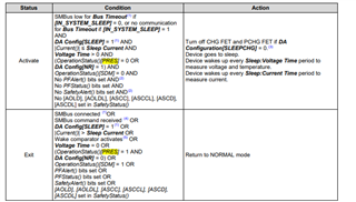
    And one more thing, sir whether we can  change  the BMS logic so within maybe 20 minutes of the PRES pin being released – we put the battery BMS into sleep mode and only wake it again when the PRES pin is triggered again ? Whether it is possible?

    Sir, is there any document related to active cell balancing ckt ideas which we can implement in our bms design?.
    I am attaching my schematic and layout for your reference please let me know if you have found any thing.2477.BMS.pdf4544.OGI_BMS.PcbDoc

    Waiting for your response,

    Regards,
    Shubham  

  • Hi Shubham,

    I wanted to ask, I see in your design that there is a R3 resistor that is a jumper. Is this jumper place on the board? Also, can you confirm measuring the pack pin to ensure no current is being pulled?

    And one more thing, sir whether we can  change  the BMS logic so within maybe 20 minutes of the PRES pin being released – we put the battery BMS into sleep mode and only wake it again when the PRES pin is triggered again ? Whether it is possible?

    I do not think this will be possible to implement based on the requirements to enter and exit sleep mode on the device.

    Sir, is there any document related to active cell balancing ckt ideas which we can implement in our bms design?.

    Yes, we have this documentation: https://www.ti.com/lit/an/slua420a/slua420a.pdf

    Regards,

    Nick Richards