This thread has been locked.

If you have a related question, please click the "Ask a related question" button in the top right corner. The newly created question will be automatically linked to this question.

TPSM33625: Problem with TPSM33625 Module

Part Number: TPSM33625

Tool/software:

Hi,

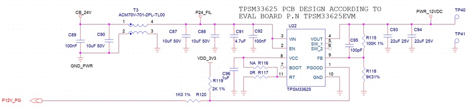
In a new card that just arrived from assembly, a conversion circuit from 24V to 12V.
The problem is that for some reason the circuit is in DROPOUT mode, meaning the output follows the input (minus DROPOUT voltage) even when the input is significantly higher than 12V + dropout.

The voltage divider for FB works correctly. Its value is proportional to the output voltage and reaches values ​​much higher than 1V.

On the SW pins there is a PWM close to 100%, meaning thin negative pulses, most of the time at 1.

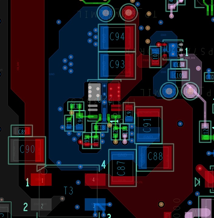
The circuit is completely the same as in the Eval board except that in the Evaluation card they shorted the 2 SW pins.

Schematic and relevant area on the PCB are attached.

Can you advice what could cause such behavior and how to solve it?

Thanx,

Eli.

  • Hello Eli,

    Are you able to share oscilloscope captures on the SW pin? 

    With regard to the schematic and layout, make sure that your voltage on the FB pin of the device is connected on the PCB. I can't see where the feedback trace is routed to on the PCB and the issue you are experiencing seems like feedback it is feedback related. Do you have specific feedback values measured on the pin of the device which you saw in your testing?

    It looks like the input filter does not have any damping. Usually input filters require a damping capacitor after the filter inductance. Please refer to the following application note: https://www.ti.com/lit/an/snva489c/snva489c.pdf

    Best regards,

    Ridge

  • Hi, Rudge,

    The inductance of the input CM and all the capacitors isn't enough for damping and can it cause such behaviour?

    I'll measure and take some pictures from oscilloscope at Sunday.

    Thanx,

    Eli. 

  • Hi Eli,

    The damping is done by the ESR of filter and it is used to prevent the filter from causing stability issues with the buck converter. 

    The feedforward capacitance is also fairly large. Have you tried reducing or removing that capacitance? Sometimes too large of a CFF value can cause issues as well. 

    When you have measurements, please share them here and I will review.

    Best regards,

    Ridge

  • Hi, Ridge,

    Removing the CFF solved the problem, now it produce 12V as required.

    Thank You.