This thread has been locked.

If you have a related question, please click the "Ask a related question" button in the top right corner. The newly created question will be automatically linked to this question.

TPS65987DDK: Program FW into an empty flash via I2C

Part Number: TPS65987DDK
Other Parts Discussed in Thread: TPS65988, TPS65987, TPS65987D

Tool/software:

Hi

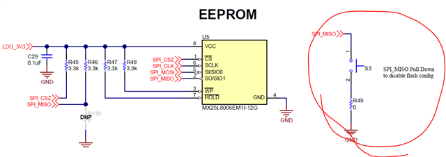
I'm designing a USB PD application board with TPS65987DDK.

Is it possible to program FW into an empty flash via I2C2 of TPS65987DDK from external CPU?

I referred to the document "TPS65987 and TPS65988 SPI Flash Firmware Update Over I2C", but I'm facing 0x2D PatchHeaderErr and cannot proceed next steps.

  • Hi Eugene,

    Yes, it is possible to load FW to an empty flash by sending commands to I2C2 of the PD controller. Are you using the FLxx commands or PBmx commands? The FLxx commands should be used when loading to flash memory.

    Please send me a list of the commands you are sending and the order, and provide an I2C log. The PatchHeaderErr seems patch related, and not flash related to me, but it could be a bad header for the binary file written over I2C. Also, how was the binary you loaded generated? What "save binary" option did you use?

    Best,

    Alex

  • Hi Alex

    Thank you for your help.

    I'm using FLxx commands and Low Region with Full Header file.

    After I erase Flash again by app config tool and power on with pushing S3 button on the TPS65987EVM, the PatchHeaderErr was cleared and I could access via I2C2.

    Should I need to prepare like S3 button on my application board to access empty flash via I2C2?

  • Hi Eugene,

    You should not erase flash again. However, you do need to re-boot the PD to allow it to load the FW from flash after the FLxx process. We only load FW from flash once at boot, so re-booting PD via power cycle or "GAID" 4CC command is required.

    Not sure what you mean by "Should I need to prepare like S3 button on my application board to access empty flash via I2C2?". I2C2 is a target module and is used to communicate with the PD. PD gets data from flash using I2C3, which is the controller module.

    Best,

    Alex

  • Hi Alex

    Thank you, I'll use GAID once I succeed FLxx process.

    >>Not sure what you mean by "Should I need to prepare like S3 button on my application board to access empty flash via I2C2?".

    My explanation was not enough.

    When the flash is empty, TPS65987D woke up as "SAFE". In this case, I couldn't access flash properly via I2C2. For example, the read data was always 0 even if I wrote 1.

    However, if I re-booted with pushing S3 on the TPS65987EVM, TPS65987D woke up as "DEFAULT". And I could access flash properly via I2C2. The read data was all FF and the data was updated if I wrote.

    Thus I thought the S3 button for pull low MOSI line is necessary if I'd like to program empty flash via I2C2.

    Is my understanding correct?

  • Eugene,

    I think you are referring to SPI_MOSI. The SPI_MOSI pin is used to boot the PD controller in safe or default configurations. So you are correct. See tables below. With identical ADCIN setting, PD will boot in safe mode if Flash is empty when SPI_MOSI is high, while PD will boot in default configuration if SPI_MOSI is low. Yes, button would be the right solution here.

    Best,

    Alex

  • Hi Alex

    Thank you I understand TPS65987D will boot in safe mode if Flash is empty when SPI_MOSI is high.

    Is there any way to access TPS65987D via I2C2 while it's in safe mode?

  • Hi Eugene,

    I2C2 should be working in safe configuration, but I will double check. Can you send an I2C capture/log using a logic analyzer showing writes/reads on I2C2 in this state? Does TPS65987D ACK or NAK the transactions? What does reading PD register 0x03 return?

    Best,

    Alex

  • Hi Alex

    Thank you for your support.

    In safe configuration with empty flash, TPS65987D returns NACK for 0x03 access. (waveform1)

    Once I asserted HRESET, then TPS65987D became to respond ACK, and the value of the register 0x03 was 41 50 50 20.

    However, I couldn't program Flash by FLwd.
    TPS65987D also returned ACK to FLwd and FLrd but the data was all 0x00 even if I wrote data to Flash. In this situation I2C waveform became weird. The interval between address and R/W bit became extended. It looks PDC outputs clock stretching. (waveform2 and 3)

    How can I program FW to flash in safe configuration?

  • Hi Eugene,

    I am checking internally on PD state in safe configuration and whether FLxx commands should work. Will update you by EOD tomorrow.

    Best,

    Alex

  • Hi Eugene,

    I checked internally and unfortunately, the FLxx commands for flash update do not work when PD boots in safe configuration with an empty flash. In safe configuration, TPS65987D is designed to boot while loading FW from flash. With an empty flash, PD cannot find any FW to load and is not enabled. TPS65987D is not designed to be able to load an empty flash after booting, but only to update a existing PD FW stored in flash. If flash is empty on boot, PD considers there to be no flash available, so it will expect a host EC or MCU to patch its SRAM directly using the PTCx commands.

    One thing you can try is to use the "Infinite Wait" configuration instead of the "Safe Configuration". This will put the PD in a different state at boot with empty flash that may allow the FLxx commands to work properly.

    Best,

    Alex

  • Hi Alex 

    Thank you, I understand.

    I have one more question.

    When PDC boots in "infinite wait" or "safe", PDC returns NACK for I2C2 access. If I asserted HRESET once, then PDC becomes to respond ACK.

    Is this also limitation of TPS65987D?

  • Hi Eugene,

    The PD should not be NACKing on I2C2 after booting from Infinite Wait. In safe configuration, NACKing is normal.

    Have you tried using I2C1? Also, when you boot the board/PD, is it being powered on from system side or through type-C port?

    Best,

    Alex

  • Hi Alex

    Do you mean the following scenario is the TPS65987D spec?

    1. Erase Flash

    2. Power on and PDC enters safe mode.

    3. External CPU access 0x03 register of PDC via I2C and PDC replies NACK.

    4. External CPU assert HRESET pulse to PDC.

    5. External CPU access 0x03 register of PDC via I2C and PDC replies ACK.  

  • Hi Eugene, 

    I checked internally and even in safe configuration, PD should be responding on I2C with ACKs. If PD is NACK'ing on I2C after booting up, then the PD did not boot correctly. This would explain why after the HRESET pin is toggled high/low, the PD begins responding on I2C. FLxx still does not work with Safe Configuration.

    I don't believe I have asked you this, but are you testing on EVM or a custom board? If you are testing on a custom board, has this scenario worked on EVM?

    Best,

    Alex

  • Hi Alex

    Thank you for your information.

    I'm testing on EVM with my custom CPU board to control I2C. I'll check power sequence again whether there is violation.

  • Hi Eugene,

    When using EVM, be careful of the ADCIN settings when using the "Disable Flash Config" button press during boot. Using the button simulates an empty flash, but also changes the ADCIN settings because it pulls down SPI pin.

    Best,

    Alex