This thread has been locked.

If you have a related question, please click the "Ask a related question" button in the top right corner. The newly created question will be automatically linked to this question.

LMR43610: Inrush current?

Part Number: LMR43610

Tool/software:

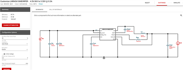
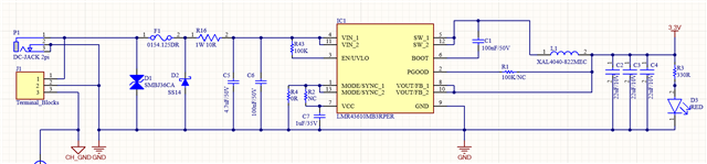
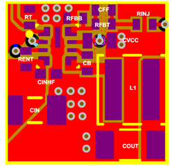
Hi I'm using LMR43610MB3RPER.
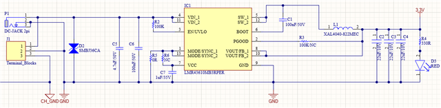
Input : 5~36V

Output : 3.3V / 0.3A MAX

when I supply 5V it works fine but supply over 12V LMR43610MB3RPER always damaged(Outputs 3.3V and GND are shorted).

If I apply 5V and then increase the voltage to 36V, there is no problem, but if I apply more than 10~12V at the first power up, there is a problem.

I know the LMR43610MB3RPER has a soft start feature, is there any reason to suspect why this is happening?

  • Hello,

    It appears that the device is experiencing electrical overstress. Are there any significant line transients in this system? The device has a current limit protection feature which protects the buck in the event of a short on the output. 

    With regard to the schematic, the inductor value is oversized. For 1MHz, Vout=3.3V, an inductance of 4.7uH is recommended. When sizing the inductor, make sure to design for the maximum output current of the device even if you plan to operate at smaller loads. Also, the TVS diode in you schematic has a clamping voltage of 58V. If you are expecting large transients on the input, a clamping voltage of 58V far exceeds the absolute maximum rating of Vin=42V for the buck converter (See Section 7 of datasheet). 

    Are you able to share the layout for this design?

    Best regards,

    Ridge

  • Thanks for your reply.

    The inductor value is set by WEBENCH

    could you tell me why the webench's inductor selection is worng?

    And the design file that you said me, mean gerber file?

    Thanks

  • Hello,

    The Webench is not wrong. Webench designs for the operating conditions that are input to the simulator. In this case, it looks like 0.3A was set as the maximum output current. Generally, it is recommended to design for the full output current of the device and then use the light load you planned for. I recommend designing the inductor for the 1A maximum load.

    An image of the layout or the gerber files would work.

    Best regards,

    Ridge

  • when I changed 1A maximum load, webench still show me the 8.2uH inductor value.

  • Hello,

    I was referencing Table 9-4 in the datasheet. It looks like Webench is designing for the minimum current ripple. I double checked with calculations using Equation 7. Use the Webench value for better current ripple performance at 1A. The recommendation in the table represents both the 1A and 2A variants.

    Are you able to share the layout?

    Best regards,

    Ridge

  • 4265.Gerber.zip

    This is my gerber file and schematic(only LMR43610MB3RPER).

  • R16 is replaced 0R not 10R.

  • Hello,

    For the layout:

    • Input capacitors should be moved closer to the IC
    • FB trace from Vout could be shortened and routed more directly but it doesn't look to be causing this issue.
    • VCC cap should be moved closer to the IC

    Here is the datasheet layout for reference

    When the board is not powered on, are you able to detect a short from GND to Vout? Have you tested your design on the device EVM? I recommend configuring an EVM for your application to see if the issue persists. It may be something on the load side of the converter.

    Best regards,

    Ridge

  • Hello,

    Since we have not heard from you in a while I will be closing this thread. If you have more questions, you can re-open this thread by replying or create a new thread.

    Best regards,

    Ridge