This thread has been locked.
If you have a related question, please click the "Ask a related question" button in the top right corner. The newly created question will be automatically linked to this question.
Tool/software:
Dear All,
we are finishing to design a power supply at 30V with max 13A in output, with 24V batteries as back-up.
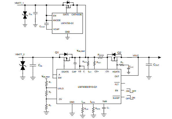
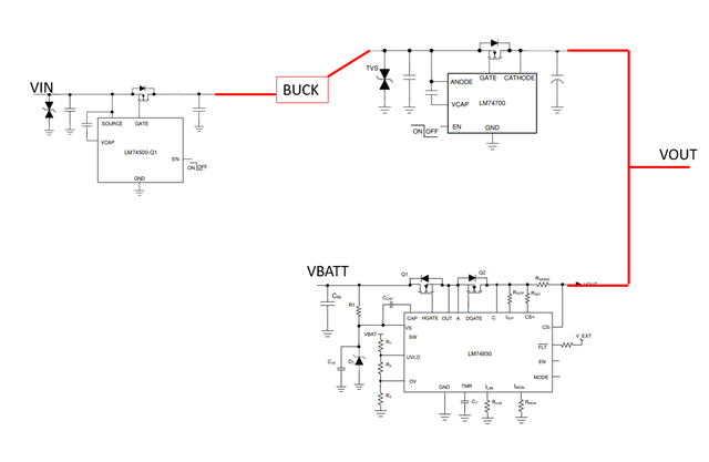
Normally to protect the power supply again the polarity inversion of batteries is used glass fuse + diode. The main problem is the installer man can replace the fuse with different value with the risk to damage the power supply. To avoid this, we want to evaluate to replace glass fuse with electronic polarity inversion block. One chip that I checke is LM74930. If I understood well, this chip is ideal for our application...
The main problem, is where apply the power supply to charge the batteries, considering the topology of battery charger is to apply the voltage in dipendence of the status of batteries and its cherger phase, using a shuint to monitoring the current. The dc-dc step-onw used is LM5149. I think to apply the voltage, from LM5149, in the middle of B2B mosfet network and before the shunt (seeing frombatteries) using a properly separateshunt, because the currentvalue is different!
Which is your opinion, please?
Thank You and Best Regards
Federico Battaglin
Hi Federico,
Welcome to E2E!
Thanks for showing interest in LM74930. Can you share any block diagram of your power supply?
Regards,
Shiven Dhir
Dear Shiven,
thank You for your welcome!
In attachment there's the block diagram of this power supply...
So, as short circuit protection on output, I'm evaluating TPS48111.
But for protection against batteries invertion, one choice should be LM749xx...
Thank You and Best Regards
Federico
Hi Federico,
Looks like you are trying to achieve this configuration. You can OR the batteries at the common drain point.
Design #4
Addressing Automotive Reverse Battery Protection Topologies with LM749x0-Q1
Regards,
Shiven Dhir
Dear Shiven,
thank You for this diagram, that I just saw reading the application notes...
But in our case, the topology is not in OR, but the buck (LM5149) charge the batteries and fix the voltage in the ouput. The output voltage is the batteries voltage.
So the problem is the connection between LM749xx to the LM5149...
Thank You an Best Regards
Federico
Hi Federico,
I am unsure if I am on the right track of understanding your system, please correct me If I am wrong, Batteries are just a backup power source, and main power source is BUCK? and you want to protect BUCK from negative polarity, right?
Also, BUCK will be the one to charge batteries also.
Regards,
Shiven Dhir
Hi Federico,
In that case, please look at the block diagram below.
Buck is protected from reverse polarity by LM74500-Q1.
Batteries and BUCK are ORed for redundant supply.
Batteries can be charged by BUCK by toggling the MODE pin and enabling reverse current flow into the battery to charge them.
Does this fulfill what you were looking for?
Regards,
Shiven Dhir
Dear Shiven,
thank You a lot... I think the diagram is very ok!
Best Regards
Federico