This thread has been locked.

If you have a related question, please click the "Ask a related question" button in the top right corner. The newly created question will be automatically linked to this question.

UCC25640EVM-020: QUESTION : Schematic part for standby mode

Part Number: UCC25640EVM-020
Other Parts Discussed in Thread: UCC256403

Tool/software:

Hello TI,


I have several questions about EVM for the UCC25640X:


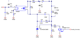
1- What is the purpose of the standby function? Is the UCC25640X required to have an external circuit of this type?


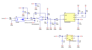
2- Does the UCC256403 -> HV pin have to be connected to ground?


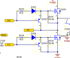
3 - Is the diode circuit on the gate input of the primary MOSFET necessary? Could you explain in more detail? I've also seen assemblies with a bipolar. Can you explain this too?


I wish you a good day,

Best regards

  • Hello,

    Your inquiry is under review and I will get back to you shortly.

    Regards,

  • Hello,

    1. Section 10.2 of the EVM user's guide explains what this circuitry is for.  The user's guide can be found at the following link.

    https://www.ti.com/lit/ug/sluubx3b/sluubx3b.pdf

    2. The HV pin is used for JFET charging of the VCC pin for boot strap startup.  More information can be found in the UCC25640x data sheet regarding its function.  You can connect it to the DC input voltage or off a full wave rectifier output if your design is powered by the AC line.

    https://www.ti.com/lit/gpn/ucc256402

    3. The circuit on the left is from the EVM.  The diodes are used for fast FET turnoff.

    The circuit on the left in 3 provides fast FET turnoff with external PNP transistors.

    Both circuits will work.  The one with the PNP transistors is used to provide greater FET gate discharge current.

    Regards,