Other Parts Discussed in Thread: LM74800-Q1
Tool/software:
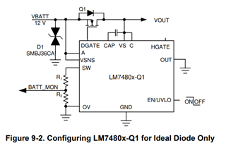
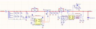
Hi, please review the schematic below in particular for reverse polarity protection up to 45V. Some parts of the actual schematic (bypass capacitors and input/output filters are not shown).
Tool/software:
Hi, please review the schematic below in particular for reverse polarity protection up to 45V. Some parts of the actual schematic (bypass capacitors and input/output filters are not shown).