This thread has been locked.

If you have a related question, please click the "Ask a related question" button in the top right corner. The newly created question will be automatically linked to this question.

TPS23755: Buck Converter Design

Part Number: TPS23755

Tool/software:

Dear team,

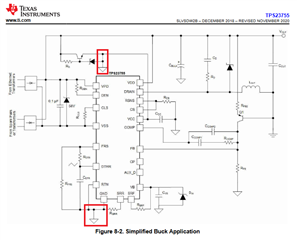
I would like to design a POE PD circuit with the TPS23755 in a Buck converter topology as proposed in the datasheet.

I already chose some components (as passive components for detection, power class and some diodes, transistors). However, for the other components, I did not find any application notes giving information for the Buck design using the TPS23755. There is only information for the Flyback application.

On the other hand, I think I found a little mistake in the datasheet : the emitter of the transistor supplying the VCC pin of the component in the Buck topology is linked to same ground reference as the RTN/GND pin of the component as on the picture attached. I think the emitter should not be linked to the ground reference to be able to supply the VCC pin.

Thank you very much,

Best regards,

Benjamin

  • Hi Benjamin,

    Thanks for your question. The buck converter is low-side switching buck (high side is a Schottky diode), so the VCC refers to the low-side DC bus. 

    Please find attached reference design which may be helpful. Feel free to let us know if you have any further questions. 

    0702.PSIL048E1(001)_Sch.PDF

    Best regards,

    Diang 

  • Hi,

    Thank you for the file with the reference design, it will be helpfull.
    For the output voltage, I would like to have a voltage near 12V so, I think that I should use a R12 resistor of  16.2 KOhms and increase the inductance to 15µH. Could you confirm my values ?

    Moreover, could I use the AUX_D input with an optocoupler and the AUX_V output to either force the voltage on the FB pin to 0V to 'stop' the DC/DC converter or command a switch circuit when a other power supply circuit with a 'higher priority' is used ?

    Best regards,

    Benjamin

  • Hi Benjamin,

    PoE PD apps expert Diang is out of office on travel. Please expect some delays in his response. Thank you for your patience! 

    Regards,

    Brandon

  • Hi Benjamin,

    Thanks for your patience.

    "For the output voltage, I would like to have a voltage near 12V so, I think that I should use a R12 resistor of 16.2 KOhms and increase the inductance to 15µH. Could you confirm my values ?"

    - 16.2 kohm looks correct to me. The load current also influence the inductance value. 12uH sounds a reasonable value at 700kHz frequency and 1A output.

    "Moreover, could I use the AUX_D input with an optocoupler and the AUX_V output to either force the voltage on the FB pin to 0V to 'stop' the DC/DC converter or command a switch circuit when a other power supply circuit with a 'higher priority' is used ?" 

     - It is more common to connect AUX_V with a resistor to FB. When AUX_D ties to RTN, the DC/DC has 12V output; when AUX_D is open circuit, PoE output will be low and be considered as lower priority. You can make 1.75V / (R2||R3) * R1 = 12V - 0.7V at 12V out, and 1.75V/R2*R1 = 12V - 0.7 when lower priority.   

    Best regards,

    Diang

  • Hi,

    Thank you for your feedbacks.

    I think I will need to increase the value of the inductor and of the switching frequency because, with your values, I will have a ripple current equal to about 1.13A and the circuit I am designing will consume a maximum current of 0.3-0.4 mA at 12V, so I need a ripple current near 200-300 mA.

    If my calculations are correct, I will need an inductor equal to 22µH with a switching frequency of 1.8MHz (and so a R21 resistor of 8.2 kOhms) to have a ripple current near 235mA.

    Best regards,

    Benjamin

  • Hi Benjamin,

    Thanks for your reply.

    I do not think the TPS23755 can work at 1.8MHz with a good frequency accuracy. It is recommended to limit the SW frequency below 800 kHz. 

    Below is a inductor current waveform for 12V 0.3A output at 800kHz and 100uH inductor. You may further increase the inductance and reduce the SW frequency.

    Best regards,

    Diang

  • Hi Diang,

    Thank you for all your feedbacks, they were helpful.

    Indeed, I will use an inductor of 100µH at 700kHz (and so a current ripple near 135mA for an input voltage of 57V) to start with the first prototype and the values (the inductance and the frequency) may evolve with the tests after.

    Best regards,

    Benjamin

  • Hi Benjamin,

    Thanks for your reply. 

    I will close this thread for now. Please reply or open a new thread if you have further questions.

    Best regards,

    Diang