Other Parts Discussed in Thread: LM25148
Tool/software:
HI sir.
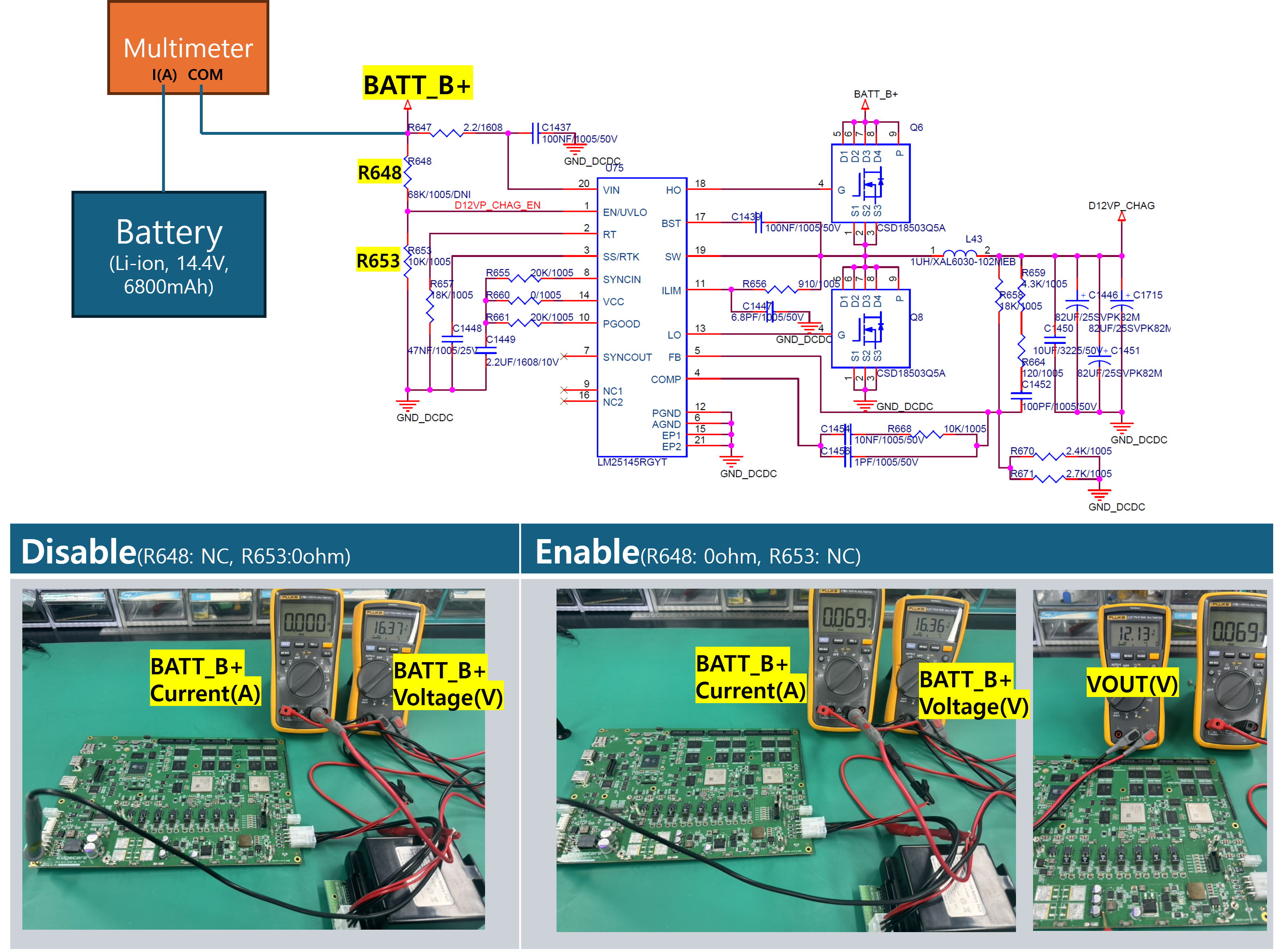
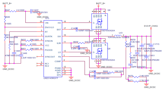
I am using LM25145 to generate a 12V output. The input voltage is from a battery (13~17V).
The LM25145 consumes around 70mA of current when there is no load on the output.
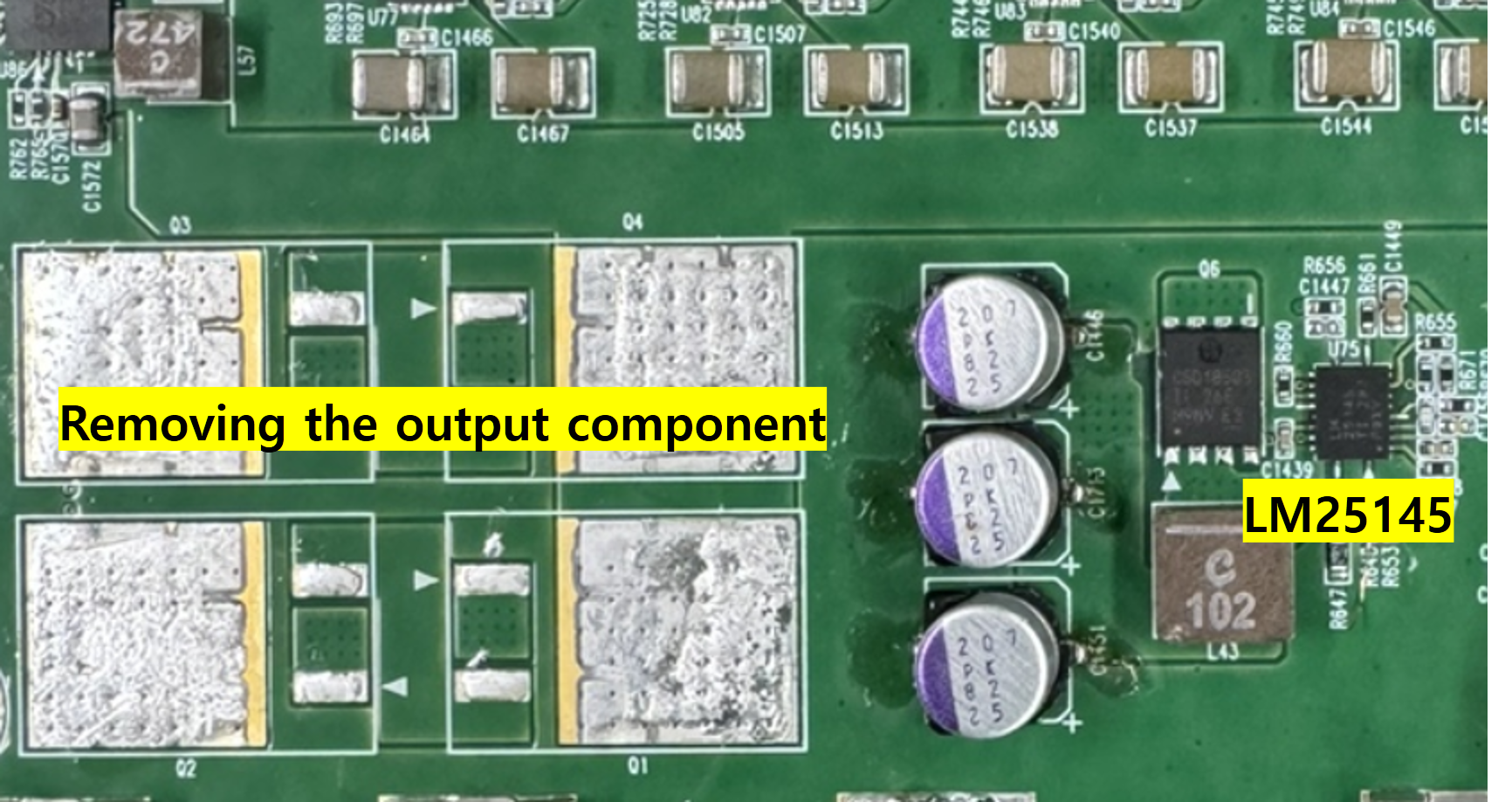
All output stage components were removed to eliminate the load.
Inquiring about the cause of power consumption when there is no load.
The circuit diagram is as follows.
Thanks.