Tool/software:
Hi Team,
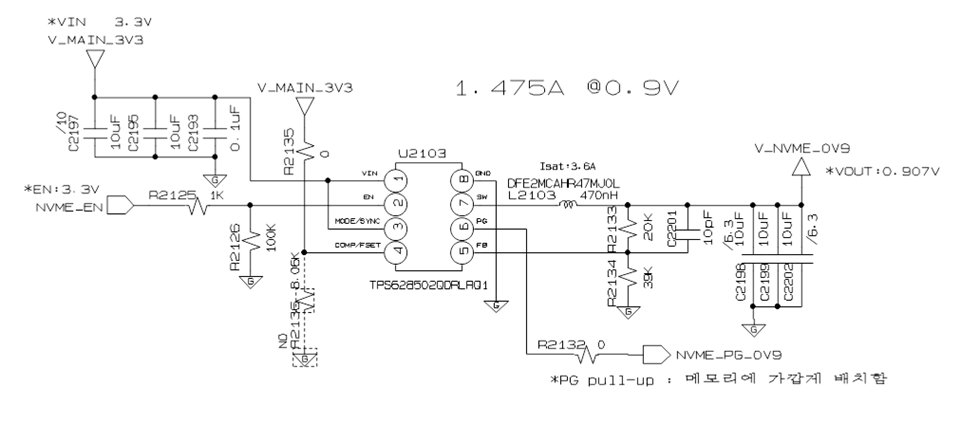
Could you please help to review this schematic?
If you need any more information, please let me know.
Sw Freq 2.25MHz
Max ambient temperature. 85 ‘C

This thread has been locked.
If you have a related question, please click the "Ask a related question" button in the top right corner. The newly created question will be automatically linked to this question.
Tool/software:
Hi Team,
Could you please help to review this schematic?
If you need any more information, please let me know.
Sw Freq 2.25MHz
Max ambient temperature. 85 ‘C

Hi,
- Could you please share customer, project and application details?
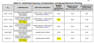
- When COMP pin is tied to Vin, the minimum effective output capacitance for Vout < 1 V should be 30uF. With the current 3*10uF, you will not satisfy this requirement.
3*10uF is sufficient when Rcf = 8.06k.
Rest seems fine.
Thanks,
Febin
Adding capacitor is pretty difficult for customer, so adjust RCF is proper.
Vin=3.3V, Vout=0.907V
SSC enable
Could you please calculate Rcf and SW frequency?
Hi Dustin,
For SSC enabled condition, the minimum effective output capacitance for Vout < 1 V should be 30uF.

Thanks,
Febin
Hi Febin,
For SSC,
1.

2.

Questions
- What is the best option (1 or 2) for 3* 10uF? Since customer dont want to add cap but want to enable SSC.
- How about using Rcf range 10kohm ~ 15kohm?
- Is there any other opinion for 3* 10uF and enable SSC?
Hi Dustin,
What is the best option (1 or 2) for 3* 10uF? Since customer dont want to add cap but want to enable SSC.
For SSC enabled config, recommendation is 30uF.
If the customer wants to use a lower Cout, I would suggest to confirm that loop stability and transient performance is as expected in his application.
How about using Rcf range 10kohm ~ 15kohm?
Please use only recommended Rcf values.
Is there any other opinion for 3* 10uF and enable SSC?
Are there any distributed capacitors on this rail?
Thanks,
Febin