This thread has been locked.

If you have a related question, please click the "Ask a related question" button in the top right corner. The newly created question will be automatically linked to this question.

LM2596: Isolating a buck regulator

Part Number: LM2596

Tool/software:

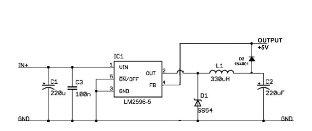
I am powering a board with 5V from an LM2596-5. Reprogramming is by a USB connection to the board, during which time the 12V supply to the LM2596 is grounded through the resistance of other circuitry, and the board's 5V power comes from the USB.

Can I rely on the LM2596 output terminal allowing this without damage or excessive (>100mA) power loss?

If not, is it safe to insert a 1N4001 (or similar) between the output terminal and capacitor of the LM2596 and its feedback terminal, and take my regulated 5V output from its cathode when not using USB power?

  • Hello,

    Do not connect a diode between the output of the buck converter and the FB pin. FB must be connected as recommended in the datasheet.

    If you expect the input to fall while a secondary supply takes over on the output, then a UVLO divider should be included on the input of the buck converter. The UVLO divider will ensure that the buck is disabled when the input falls below a certain value. See Section 8.3.2 of the datasheet for reference. 

    Best regards,

    Ridge

  • Thank you for such a quick response. I had considered the UVLO circuit but the UVLO works when there is sufficient voltage on pin 1 for the device to sense a positive OFF voltage on pin 5. I am concerned with the device behaviour when pin 1 not connected to a supply, and is either floating or grounded via the undetermined resistance of other circuitry on the 12V supply, and +5V is applied to pins 2 & 4. Is it safe to do this? I am unable to find anything in the data sheet indicating whether it is or is not.

    I am not concerned with problems arising from the presence of the +12V (and therefore two competing +5V sources) during USB programming as there will be a simple mechanical interlock to prevent this (a sliding shutter prevents simultaneous connections to the +12V input plug and the USB port).

    I would be interested to know why it is inadvisable to have a high current diode in the feedback path, defining the output voltage at the diode's cathode rather than at the actual "OUTPUT" terminal (pin 2), and isolating this terminal (although not the feedback input - pin 4) from the +5V line when the LM2596 is unpowered.

    Best wishes - James

  • Hello James,

    When the input falls while the output rail is pre-biased, you may need a shottky diode from SW to Vin in order to prevent the HS switch body diode from conducting during the case that Vin < Vout. Alternatively, you could use a diode in series with the output to prevent any reverse current flow. 

    The device is designed for FB to be connected directly to the output of the buck over the output capacitors. It is not recommended to impede the FB path for proper regulation of the device. If this is to protect the buck from reverse current when the device is disabled and the secondary supply for 5V takes over, then the diode should be placed after the output of the buck. It looks like the diode is meant to protect from reverse currents. In that case connecting FB directly to Vout of the buck and placing the diode in series with the load is the recommended solution.

    Best regards,

    Ridge

  • The problem with a diode in the regulated output is that the diode voltage drop, and hence the regulated supply, will vary with load current. My application requires reasonably stable supply over two decades of current change (10mA - 1A). The voltage of a 1N4001 changes logarithmically by around 100mV/decade in this region. So a post regulation diode isn't really practicable.

    But if a diode in series with the input provides adequate protection I don't need one in the output. Thank you, my problem is solved - although I'd be interested to know if there's any particular need for a Schottky diode rather than a plain vanilla 1N4000 or one of its higher current brothers. The efficiency is higher with the Schottky, but there isn't a headroom issue and most of the time I'll be running at low currents. I use a switching, rather than an analog series, regulator to avoid the need for thermal management for the occasional minutes or ten of high current.

    Best wishes - James

  • Hi James,

    The schottky is usually recommended for the low forward voltage drop. If you are unconcerned about minimizing the drop on the input then you may not need a schottky. Make sure that the diode is connected before the input capacitors to the buck converter. The input capacitors need to be placed as close to the IC as possible when you create the layout.

    I drew the diode into the schematic to show what I mean:

    Best regards,

    Ridge

  • Thank you - James