This thread has been locked.

If you have a related question, please click the "Ask a related question" button in the top right corner. The newly created question will be automatically linked to this question.

BQ25180: Use push button to exit ship mode but also connect button to MCU for reading fast button events.

Part Number: BQ25180
Other Parts Discussed in Thread: BQ25150, SN74LVC1G126

Tool/software:

I want to use a push button connected to TS/MR to exit ship mode but also be able to read the push button state on the MCU.
Looking at the datasheet it seems tWAKE1 can only be set to 300ms and I really need to be able to detect faster events so I can't rely on the BQ25180 to do it.

What circuit can I use to connect a push button to TS/MR so end users can exit ship mode and also reliably read out the button with an MCU where it's used as a navigation button?

In the linked thread a circuit is given with two FETs and a push button that connects to VDD, however when in ship mode it seems to me VDD isn't available and that circuit uses VDD to drive the gate but VDD won't be available since we're in ship mode?

Ideally I'd want the button to read high on the MCU side when pressed.

If it helps: TS function won't be needed so that will be tied to a 10k resistor as suggested in the datasheet.

  • Hi Robert,

    Just to make sure I understand correctly, for this circuit you will have a signal directly available from your MCU to probe the button / MR signals to tell when they are high/low? Also, I'm not sure what linked thread you may be referring to, I don't really see it. VDD isn't present on the BQ25180, is this in reference to a BQ25150 circuit?

    Best Regards,

    Juan Ospina

  • Hi Juan,

    Correct, I want to use one of the MCU's pins to read the state of a push button (it's used as an OK/Enter button in the firmware running on the MCU) but I also want that button to serve as the button to get the BQ25180 out of Ship Mode.

    Regarding the linked thread and the circuit I'm referring to: At the top it should say "Original Question" and a link below it to the thread where I found the circuit I'm referring to. Here's the link since it doesn't seem to show up for you: https://e2e.ti.com/support/power-management-group/power-management/f/power-management-forum/1164574/bq25180-able-to-place-pullup-resistor-to-mr-pin

  • Hi Robert,

    I see. In this case I believe VDD should refer to a pull up rail such as your MCUs pull up rail. The idea is the push button will drive the FET gates and short TSMR to ground while also pulling down the MCU_INPUT pin as an indicator.

    In order to have it drive the TS/MR you can connect it directly to the TSMR FET gate in order to drive it as an output and also sense the voltage as an input. One thing to watch out while driving it as an output would be checking that the button being pushed at the same time as the GPIO being driven does not cause any unexpected interactions in the MCU. If the GPIO is configured to an internal pull up to the same rail as VDD then this may be ok.

    Best Regards,

    Juan Ospina

  • Thanks Juan,

    I'm still not sure about VDD though. I get that VDD could be the MCU power rail but during Ship Mode the BQ25180's SYS pin will not be connected so where does the voltage for VDD then come from to drive the gate and pull TS/MR low to exit Ship Mode?

  • Hi Robert,

    The pull up rail for your push button can be your battery. In that case you can use the referenced circuit with VDD for the PB pull up to be BAT and the VDD for the MCU FET and Pull up to be the MCU''s power rail.

    Best Regards,

    Juan Ospina

  • Hi Juan,

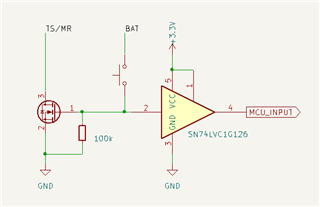
    That might work! As I mentioned in my opening post, one of the requirements is that the MCU sees the button as high when pressed. I put together a circuit with the TI SN74LVC1G126 buffer to protect the MCU from the higher BAT voltage but also to prevent it from being back powered when the BQ25180 is in Ship Mode and somebody presses/holds the button. The buffer's datasheet mentions 'Ioff functionality' so that should work, right?

    Here's the circuit I came up with:

    Do you see anything wrong with using that to solve my problem?

    Thanks.

  • Hi Robert,

    I believe that should work. When the button is pressed it's important to note that there will be some discharge from the BAT to GND for the duration of the press. I would also consider a small resistance between the push button and the BAT. I believe that should work for your application though.

    Best Regards,

    Juan Ospina