Tool/software:
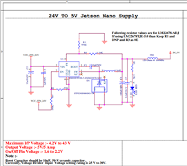
I am writing to seek your assistance regarding a problem we are encountering with the LM22678TJE-5.0 IC in our design. Below, I have outlined the details of our setup and the specific issues we are facing.
Power Supply Details
We are using the LM22678TJE-5.0 IC in a PCB design powered by a battery system with the following specifications:
- Voltage: 25.9V nominal, with a maximum input of 29.5V.
- Current Capacity: The battery is capable of delivering up to 60A.
- Protection: A 5A fuse is installed between the PCB and the battery to provide overcurrent protection.
Prototype Testing
During the prototype phase, we tested the IC with a high resistance load:
- Performance: The IC performed as expected under the high current conditions without any signs of damage.
Field Failures
Despite the successful prototype testing, we have observed the following issues in the field:
- Failures: The LM22678TJE-5.0 IC has been failed to in our one of the end Product. The IC is failing to provide the expected 5V output and it seems like it is internally damaged.
- Handling: These failures occur without any physical handling or alterations by our customers, indicating potential issues inherent to the operational environment.
Specific Concerns
We are looking to understand the possible causes of these failures, and we have two main areas of concern
-
Voltage Transients or Spikes:
- Is it possible that voltage transients or spikes in the power supply could be contributing to these IC failures?
- Could you recommend any additional protective measures to mitigate these potential issues?
We would appreciate your insights and any suggestions you can provide to help us resolve these issues.
I am attaching the circuit diagram for your reference.
.