This thread has been locked.

If you have a related question, please click the "Ask a related question" button in the top right corner. The newly created question will be automatically linked to this question.

LM317: Using an LM317 as a current limiter

Part Number: LM317

Tool/software:

Hello,

I'm trying out an LM317 as a current limiter (approx. 1A max) for a purely resistive load. I've set up the design as per the datasheet (see schematic attached here).

My input voltage is +36Vdc from a lab power supply, with its own current limiter set to 2A. Vload is around +34.3Vdc, as expected.

When I try a load of 48 Ohms, I get the current as expected - approx. 0.7A. However, when I try loads of 24 Ohms and even less resistance, I hit the 2A limit on the lab power supply. I thought the circuit here would limit the current to around 1A. Am I missing something?

Thanks for any insight.

  • Hi David,

    You need at least 3V from Vin to Vout to maintain regulation with the LM317.  Assuming you have that set correctly, then 36V - 3V = 33V is the maximum you can obtain on the output load.  The max output current of this device is 1.5A. Above this, you may begin entering current limit.  When you used 48 ohms on the output, you achieved 0.7A because this is ohms law when Vin - Vout = approximately 3V.  When you used 24 ohms on the output, you have 12W power dissipation across the LDO which is a lot and this is likely placing the LM317 into thermal limit.  The LM317 may enter thermal limit, turn off, then after cooling down it may turn back on and the peak current may trip the bench supply current limit.  This is probably too fast to see on the bench supply meter but if you had a current probe or voltage probe and could probe this on the oscilloscope you would see if (if thermal limit were, in fact, happening).

    Thanks,

    Stephen

  • Hi Stephen,

    Many thanks for the reply. I'm back in the office today and will do some more measurements. During all the tests mentioned above, the LM317 never got super heated, even when pulling 2A from the Lab PSU. By that I mean I could put my finger on it without getting burned (I reckon it was at 50-60°C). I'll report back later. Thanks again.

  • At 36Vdc input I tried a few different load resistances, from 1K Ohms (Iload=0.034A) down to 48 Ohms (Iload = 0.7A), and the voltage drop across the LDO is pretty constant at around 1.7V. I tried two different LDOs just to check. With a 48 Ohm load, this would mean a power dissipation in the LDO of (1.7 x 0.7) = 1.19W, which should be fine. 

    I still don't understand why, with a series resistor of 1.2 Ohms, the current limiter of the LDO isn't kicking in at 1A when the load current is much higher. I thought that was the point of this circuit.

  • Hi David,

    One clarification: this circuit is not a "current limiter" but is a "current regulator".  The LDO will regulate a constant current load (current regulator) as opposed to providing an upper bound on the maximum load current possible (current limiter).  If you need a current limiting circuit, that will be different than this one, but let me know.

    When the load resistor is 1k ohms, it makes sense to me that the load is 0.034A.  You are operating in dropout (not enough voltage from Vin to Vout) so the current regulator cannot properly regulate.

    When the load resistor is 48 ohms, it makes sense that Iload = 0.7A.  It's the same thing. 48 ohms x 0.7A = 33.6V, so you are still operating in dropout and the current regulator cannot properly regulate.

    If you operate with something like 32 ohms or 31 ohms load resistance, you should see 1A load current and 32V or 31V on the output (respectively). But you will have 4W or 5W of power dissipation across the LM317 which may cause the LDO to toggle in and out of thermal limit protection (and you should see if this is happening by monitoring Iout and Vout).

    If you are still having issues, can you provide oscilloscope plots of Vin, Vout and if possible, Iout, along with a schematic for review?

    Thanks,

    Stephen

  • Thanks for the info Stephen.

    Yes, the current limiting aspect (around 1A or 1.2A) is probably the most important aspect. I'm trying to limit board size too, so have as few components as possible, and avoid new EMC issues by adding a dc/dc switching circuit. I also can't have too much heat dissipation in this small circuit. It looks like the LM317 solution would be insufficient at 36Vdc input. Pity. Maybe split load into 2 parallel LM317s ?
    The goal of the circuit in question is to control (ON/OFF) a remote heater (30-40W) from a +36Vdc regulated power supply. The PSU can pump out nearly 10A. I may try a simple FET / resettable semi-conductor fuse solution, but not sure about the response time of these fuses. The current limiter is needed because there is a low tolerance on the special heating elements and some drop quite a few Ohms.

    Thanks

    David.

  • Hi David,

    I can help. What do you think your load impedance will be from the heater?  Is there a min/max load resistance?

    Thanks,

    Stephen

  • Hi David,

    You may not need to provide the load resistance.

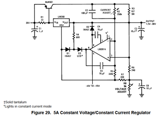
    I would take a look at Figure 29 in the LM150/350 datasheet as a starting point.  You can replace the pots with discrete resistors if you do not need any tuning.  You can use the LM317 in place of the LM150/350 here. And unless you want the LED, you can remove that too.  I have a copy of this circuit built so if you want some measurements to help your assessment, let me know. 

    Thanks,

    Stephen

  • Many thanks for the suggested circuit Stephen. I'll have a look to see if it fits, although I only have a +36Vdc supply to play with, so would have to generate the (-)ve bias voltage for the Op-amp.
    With the heating elements I'm trying out, the nominal load is 32 Ohms, but I have some that eventually drop down to less than 10 Ohms, hence my need to limit the current. I'm also looking at some other heating elements.

    Cheers

    David.

  • Hey David,

    Thanks for the update.  FYI - You can probably use a modern op-amp that will not require a negative rail.  You can submit an E2E request to the op-amp team for some options.

    Thanks,

    Stephen