This thread has been locked.

If you have a related question, please click the "Ask a related question" button in the top right corner. The newly created question will be automatically linked to this question.

BQ24735 stops charging after 50 seconds

Part Number: BQ24735
Other Parts Discussed in Thread: EV2400

Tool/software:

Hello Forum,

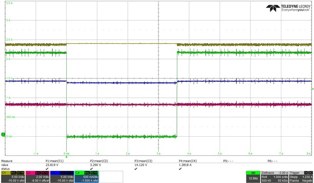
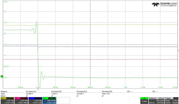
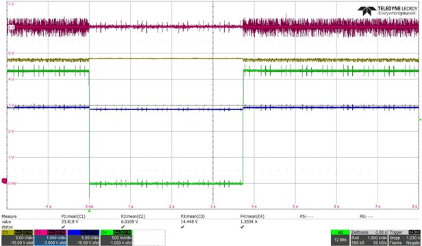
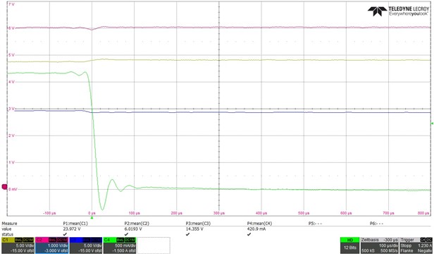
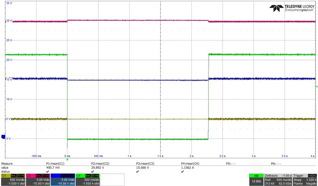
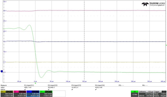
We have the BQ24735 in our design to charge a 4S1P battery. The system is supplied with 24V from a power supply unit with max. 2.7A. Charging works as desired. Strangely enough, charging always stops after 50 seconds. And is only restarted when the charging voltage and the charging current are rewritten to the registers.
We can deactivate the watchdog, but this does not change anything. We have also tried using the watchdog to write the charging voltage or the charging current or both values to the registers before the watchdog time expires.
The strange thing is that both registers are empty after 50 seconds. When the watchdog is triggered, charging is interrupted but the contents of the registers are retained.
For testing purposes, we have already disconnected the SM bus from our electronics and switched it to the EV2400 and controlled the charge controller with the battery studio. The same problems occur here.
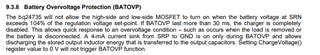
As a test, we reduced the input voltage to 21V to exclude the 24V voltage at the edge of the specification. We have also added the 20R resistor for the high side boost as a test. At the same time, we also replaced the 100nF bootstrap capacitor with a 47nF capacitor. This was also unsuccessful. I have already replaced the component on our circuit to rule out a malfunction.

I could not find any external condition that causes the loading process to be cancelled. Due to the empty registers, I assume that the module is restarting internally. But I don't know for what reason.
As a test, we have also reduced the charging current from a maximum of 2A to 500mA to rule out possible interference due to a poor layout.
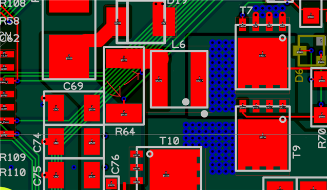
The circuit diagram shown here for our charge controller is very close to the specifications in the data sheet.  The battery, which is also queried by the processor, is also connected to the same SM bus.
The registers are set with these values:
Charge Option 0x12 0xBB32
Charge Current 0x14 0x0940
Charge Voltage 0x15 0x41A0
Input Current 0x3F 0x0780


At which point can we continue troubleshooting?


  • Brief feedback in addition to the problem.
    We had an internal discussion with our colleagues and the question arose as to whether the resonant frequency of the coil and output capacitance might be too low. However, the biasing of the capacitors was not considered.
    In addition, I also removed C74 C75. Without changing the problem. Then I also reduced the inductance L6 to 6.8µH. Unfortunately, this also did not solve the problem.

  • Hello,

    What is the battery voltage that is attached?

    Do you have a system load? Does this issue occur with/without a system load?

    Best Regards,

    Christian.

  • Hello Christian,

    I knew there were still some interesting details missing.
    Here is the data for the battery (RRC 2054) with internal BMS
    Nominal voltage 15.0V
    Nominal capacity 3200mAh
    Initial impedance <270mΩ @ 1kHz at 20°C
    Max. charge current 2170mA
    Max. charge voltage 17.4V
    Overcharge detection voltage 4420mV/cell
    Overcharge release voltage 4200mV/cell
    Overdischarge detection voltage 2750mV/cell
    Overdischarge release voltage 3000mV/cell
    Overcharge detection current 2400mA
    Overdischarge detection current 4350mA

    The system hangs on the system voltage output. We have a load of 60mA when charging with an input voltage of 24V. I would still have to test without a system load, but I can't imagine that this small load is responsible for the problem.  

    Best regards

    Philipp

  • Hello Philipp,

    Can you provide a scope capture when devic stop charging? Capture VAC,ACOK, VBAT, IBAT?

    Do you see ACOK go low?

    Best Regards,

    Christian.

  • Hello Christian,


    of course no problem I had already measured the points and saw no abnormalities.
    The first picture shows the entire interruption, in the second picture I zoomed in on the edge.
    CH 1 is the input voltage
    CH2 is ACOK
    CH3 is the battery voltage
    CH4 is the charging current

    Zoom:

    Here I have once again converted the CH2 to the Vregn voltage.
    CH 1 is the input voltage
    CH2 6V Vregn
    CH3 is the battery voltage
    CH4 is the charging current

    Zoom:

    Are the measurements enough for you or do you need more?

  • Hello Christian,

    do you have any idea where our problem might come from? We are slowly running out of time as we have to order the pilot series of pcbs.

    Best Regards, 

    Philipp 

  • Hello Philipp,

    I recommend following the schematic checklist:BQ24735_SchematicChecklist.pdf

    I noticed a few things that might cause issue including capacitors in between SRN and SRP C83/C75. R56 should be 7.5ohms, and I'm also not sure how VSYS is connected to system.

    Best Regards,

    Christian.

  • Hello Christian, 

    The capacitors between SRN and SRP are perhaps a little badly drawn. These are located behind the shunt. The shunt has two separate lines for the measurement which are not in the current path. Here is a section of the layout:

    What exactly do you mean by how +Vsys is connected to the system? Behind the fuse are various loads that can be switched and the 3.3V voltage regulator.
    The loads are interlocked by a logic circuit during charging so that they do not receive the 24V input voltage in the event of a fault.

    Where does this circuit diagram list come from? I have never seen it before?

    I don't understand how this leads to the suspension. I have used the stopwatch to look at the times from the start to the stop of charging, we always have exactly 50 seconds. To me this sounds like an internal reset or something similar, but unfortunately I can't find anything about this in the circuit diagrams in the data sheet. If the controller would work unstably or if the switch-off would be delayed when I change the charging current, then I can imagine that it is a problem with faults in the external circuitry.

    Before the question arises. I have already replaced the charge controller chip on the circuit board.

    Best Regards

    Philipp 

  • Hello Christian,

    I have now tried again.
    I first reduced the resistor R56 to 7.5R and in the second step I bridged the resistor completely. Both without any change.
    Then I went and removed the capacitor C73 as a test. This capacitor does not appear in the data sheet, in the EVAL board 1µF is installed. This was also done without a change. As a test, I then bridged the ground potentials of the input and output capacitors with a desoldering wire in addition to the circuit board. No change in behavior here either.
    I am at a loss as to what else I can test. I couldn't find any further differences in your document either.

    Best Regards

    Philipp

  • Hello Philipp,

    What is the voltage on the ILIM and SRN pin when this issue occurs?

    What is the voltage on ACDRV?

    Best Regards,

    Christian.

  • Hello Christian,

    here is another measurement with the voltages .
    I have triggered on current channel 4 so that we can see the correct time.
    CH1 shows ILIM.
    CH2 shows the SRN signal
    CH3 shows the ACDRV signal at 24V input voltage
    CH4 shows the charging current of the battery

    Best Regards

    Philipp 

  • Hello Philipp,

    The SRN voltage is 29.892V-30.048V? Is this correct?

    It looks like the device is going into BATOVP mode.

    Have you tried replacing the IC?


    Best Regards,

    Christian.

  • Hello Christian,

    Sorry, I made a mistake yesterday with CH2 and CH3...
    CH2 is the ACDRV voltage at an input voltage of 24V
    CH3 is the battery voltage measured at the SRN pin.
    Then the battery voltage is not exceeded. I suspect that at 30V the battery's BMS would also stop charging immediately.
    I have already replaced the chip. However, we have the problem on all 7 circuit boards that we have manufactured so far.

    Best Regards

    Philipp

  • Hello Philipp,

    These are the conditions to stop charging:

    According to your test the device is not running into any of these faults.The last thing to check is the TSHUT IC temperature threshold is reached. Can you measure the temperature of the IC?

    I also recommend checking the BQ24735 layout guideline:

    Another option is to order a BQ24735EVM, and see if there is an issue with the test setup.

    Best Regards,

    Christian.

  • Hello Christian,
    I did not measure the temperature on the module. However, I can touch it with my finger without any problems so that there is no temperature above 50° in the module. In addition, I have already cooled the whole circuit with cold spray during charging to prevent a possible temperature change in the component.
    I already have the Eval board on the table and it works permanently.

    I wouldn't be asking in the forum if we hadn't already tried a few things here with several colleagues.

    Best Regards

    Philipp

  • Hello Christian,


    do you have any other ideas what we can try?

    Best Regards

    Philipp

  • Hello Philipp,

    I'm reaching out to a team member, to see if they have seen a similar issue.

    Best Regards,

    Christian.

  • Hello Christian,
    I wanted to ask when I can expect an answer? Are there any new ideas as to where the problem might lie?

    Best Regards

    Philipp 

  • Hello Christian,
    I wanted to ask when I can expect an answer? Are there any new ideas as to where the problem might lie?

    Best Regards

    Philipp 

  • Hello Philipp,

    I'm sorry for the delay, We were on US holiday thus there was a delay in response.

    I spoke with a team member, and we have not seen this issue before.

    I have a few things to try:

    set REG0x12[8]=0

    set REG0x12[7]=1

    Remove D6/D4

    Remove R70/R50.


    Best Regards,

    Christian.

  • Hello Christian,

    We have implemented the suggestion here. My colleague changed the programming and I bridged the resistors R70 and R50. This means that neither the resistors nor the diodes are active.
    The behavior of the charge controller has not changed in any way. I would assume that we have only significantly degraded the EMC behavior.

    Best Regards

    Philipp

  • Hello Philipp,

    The behavior of the charge controller has not changed in any way. I would assume that we have only significantly degraded the EMC behavior.

    That is unfortunate to hear. I spoke with other team members and we have not ran into this issue before. I have a few more things to check:

    Can you provide you PCB layout.

    a scope capture of the HIDRV/LODRV signal, and the SW node when charge is disabled?

    Have you tried using a different battery or a sourcemeter to represent a battery.

    Best Regards,

    Christian. 

  • Hello Christian,

    thanks for the tips. We are now on the trail of the problem. The battery sends data every 50 seconds directly to the charge controller, which apparently can't handle it. We need to find out why we can't get the RRC battery to stop sending data. We have always assumed that the battery only sends data on request. That's why we haven't even thought about this in the least...

    Best Regards

    Philipp