Other Parts Discussed in Thread: AM62A7
Tool/software:
Hi TI expert,
There is one issue when our DUT do DV test following ISO 16750-2 2010 4.6.2 standard.
Experimental phenomenon:
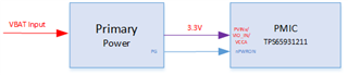
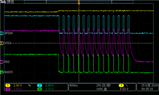
When the battery input drops near to 3.3V and keep this voltage near 5S (the power input for TPS6593-Q1 will follow the primary power output, so the voltage is near 3.2V) , then PMIC TPS6593-Q1 will go to safe recovery state after RECOV_CNT_THR reach to 15 times and then shut down all power output.
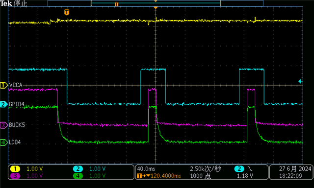
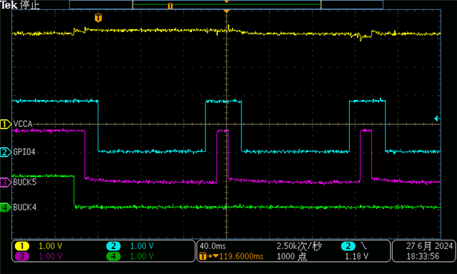
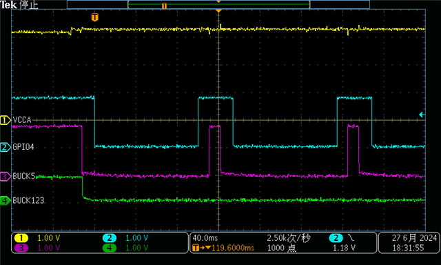
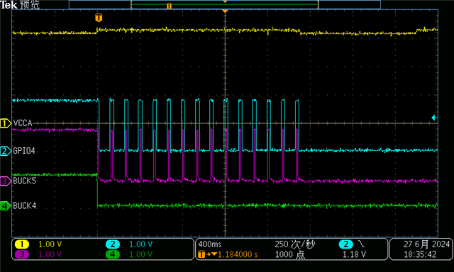
The test wave is as below: (Channel 1: VCCA of TPS6593; Channel 2: GPIO4 of TPS6593)

My question:
1. Why does the PMIC TPS6593 go to safe recovery state? Is this because the power input voltage to TPS6593 has little voltage dropping?
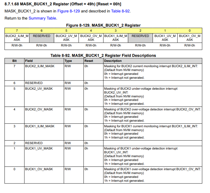
2. Can we modify some registers setting in TPS6593 side by I2C in order to prevent this behavior?