Other Parts Discussed in Thread: CSD,
Tool/software:
I am trying to control Miki Pulley's BXR-50 product, but I am inquiring because the FET is burning.
The applied circuit is as follows. If you need more information, please let me know. For convenience, we will refer to the top FET as Q1 and the bottom FET as Q2.
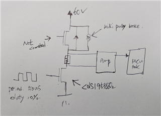
This brake sets the PWM to 10% and supplies voltage to the brake coil using a voltage control method.
The above FET has a parasitic diode and is used like a freewheeling diode.
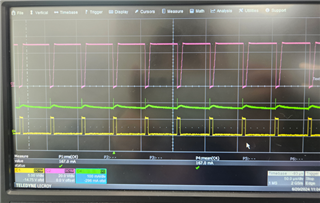
Below is the waveform.
...
Purple is the VDS voltage of Q2 FET, green is the Brake coil current, and yellow is the Q2 FET gate voltage.
First, let's provide information about the facts through various tests.
If you lower the duty to 8%, it will operate normally even after running for 12 hours.
However, at around 13%, the FET explodes after one hour of control.
The reason for setting it to 13% is that the recommended brake coil current is 200mA, so setting it to 13% produces 200mA.
When the FET used as the freewheeling diode above was removed from the PCB and operated, Q2 FET exploded. Is a freewheeling diode absolutely necessary? Q2 If the spike is below the Vds specification of the FET, there is no need to add it?
The second
I removed the FET used as a freewheeling diode and installed the US1D product. Then the Q2 FET exploded. Why?
Third, I know that the CSD FET does not fully open when the GATE voltage is 5V, and I expected that the Rds on resistance would increase and generate heat, causing the FET to explode. It's not like that. If this is true, since 5V is the maximum in the system, please recommend a FET that operates at 5V, withstands 100V withstand voltage, and has an ID of 1A or more.