This thread has been locked.

If you have a related question, please click the "Ask a related question" button in the top right corner. The newly created question will be automatically linked to this question.

UCC25660: UCC256601 does not work and is damaged.

Part Number: UCC25660

Tool/software:

Hello, this is Jeong Cheol-ho.

We are in the process of designing a 600w class using ucc256601.
When power is turned on, there is no response to the output, so I checked ucc256601 and found that pins 8 (V5P) and 10 (GNDP) are SHORT.
I'm asking because I don't know the cause.

thank you..

SCHEMATIC1 _ PFC_LLC.pdf

  • I have one more question.
    At Without HV Startup, should PFC be activated after V5P is output normally and power is supplied to LL?

  • Hello,

    Your inquiry is under review and I will get back to you shortly.

    Regards,

  • Hello,

    I reviewed the schematic and functionally it looks O.K.

    Power supply controllers will fail if the devices absolute maximums and minimums were exceeded.  More than likely this is what caused the device to be damaged.

    Is the UCC256601 the only device that failed?  

    In regards to the LLC and PFC power up sequence.  Typically the PFC is power up first.  This is because the PFC provides regulated power to the LLC.

    Please note if the LLC power up first the FET on the primary will see more current than normal.  If you over current protection is not setup correctly this could cause the FETs on the primary of the LLC to fail.

    Regards,

  • Hello,

    Yes UCC256601 is the only device that fails.

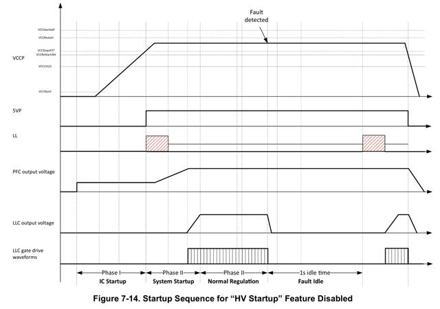
    Datasheet 33page "Figure 7-14" shows the sequence in which VCCP is supplied, 5VP and LL are output, PFC is operated, and LLC is operated.
    Isn't this a problem caused by not following this sequence?

  • Hello,

    I just want to confirm when the UCC256601 device is replace the design works O.K.?  It is very unusual that the controller fails by itself.

    You had mentioned that the 5VP was shorted to ground on the failed device.  Could you do an impedance measurement of all pins of the failed device and a non failed device?  Please make sure that ohm meter's negative lead is reference to ground.  This is so you don't forwarded bias the devices ESD diodes.

    This information will help determine if there are any other things breaking down in the UCC256601.

    In regards to figure 7-14.  The systems engineer has designed this controller to power the LLC first and then the PFC.  Thanks for pointing that out.  I was not aware of that.  However, in designs that I have done, I have powered the PFC first and then the LLC.  This is because the LLC is limited to input range of 2 to 1.  However, it is possible to design for figure 7-14; as long as, the input voltage is less then 2 to 1.

    Regards,

  • Hello,
    Devices with errors measure between 6 ohms and 450 ohms, while normal devices measure around 250 kilohms.

    Is it possible that Without HV Startup mode does not support UCC256601, but only UCC256603?

    Regards,

  • Hi Chullo,

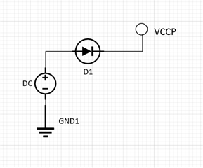
    You could power up UCC256601 without HV startup for debugging purpose. Schematic is shown below:

    You can use a DC source (15V) in series with a diode and connect to the VCCP pin of the IC directly. That way once controller starts up, diode will block the aux voltage.

    Regards

    Manikanta P

  • To this day, ucc256601 continues to be broken.
    As a result of checking the waveform at startup, it is determined that a negative voltage is generated at the HS terminal and the ucc256601 is damaged.
    I can't figure out the source of the negative voltage appearing on the HS terminal.
    Please check the waveform and reply.
    (CH1: LO, CH2: HO, CH3: HS)
    Regards

  • Hi Jeong,

    Could you share your schematic and layout files. Also, could you let me know how you are measuring these scope waveforms. Are you using Differential probe or normal probe?

    Regards

    Manikanta P

  • Hi,

    Share circuit diagrams and PCB drawings.
    I'm using a normal probe.

    Regards

    1016.SCHEMATIC1 _ PFC_LLC.pdf

    SILK TOP.pdf5621.TOP.pdf8345.BOTTOM.pdf

  • Hi Jeong,

    You shouldn't measure HO-HS with normal probe. You will have to use differential probe. By using the normal probe, you are shorting the switch node to ground.

    Could you retake the waveforms with differential probe and see if there is any issues?

    Regards

    Manikanta P

  • Hi,

    I didn't measure between HO-HS. This is a measurement of HO-GND.

    Regatds

  • Hi Jeong,

    When you measure HO-GND, during high side turn on, the voltage should be more than HS voltage. But I don't see that in your waveforms.

    What's the values of R32 and R37, C22 in your schematic?

    Regards

    Manikanta P

  • Hi,

    I understand that when measuring HO-GND, the voltage at high side turn-on should be HS voltage + GATE voltage, and the HS voltage should be the input voltage.
    I am inquiring because I do not understand how the currently designed product operates this way.
    Any help would be greatly appreciated.

    And as in the circuit diagram, the values ​​of R32 and R37 are 2ohm.
    The value of C22 is 220nF.

    Regards.

  • Hi Jeong,

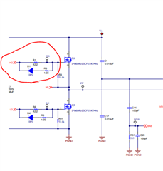
    Could you try slowing down the turn on of the switches by increasing the gate resistances. At the same time, could you also connect an anti-parallel diode as shown below to increase the turn off.

    Regards

    Manikanta P