This thread has been locked.

If you have a related question, please click the "Ask a related question" button in the top right corner. The newly created question will be automatically linked to this question.

LM5069: No Latch-Off after high overcurrent load

Part Number: LM5069
Other Parts Discussed in Thread: TPS4811-Q1

Tool/software:

Hello, i have to following test design with LM5069 as an E-Fuse to limit/break currents higher than approx. 16A for 48V nets.
In my Test-Setup i'm using an industrial 48V Power Supply with 20A and short term overload capability (50A) on the input and an electronic load in current-sink mode on the output.
Purpose of the test is to see at which current the IC switches off.
Short summary of the Problem: When the Load-Current is set to 16A, the IC latches off successfully. But when the Load-Current is increased to 18A, the IC does not stay latched off but resets itself.
This problem only occurs with an el. Load on the output, tests with hot short circuits or low resistances were successful.

Notes about the Design / Setup:

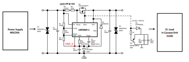
  • dv/dt is quite slow as high output capacitances up to 10-20mF need to be driven. Tests with Cout=12mF were successful.
  • Reverse polarity protection is included with D3 for the IC. Back-to-Back FET is not included as the devices intended to be attached to the output already block reverse currents by themselves.
  • D4 was added to prevent negative voltage spikes between OUT and GND_IC
  • All measurements shown below are using GND_IC as reference level, not GND.

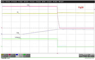
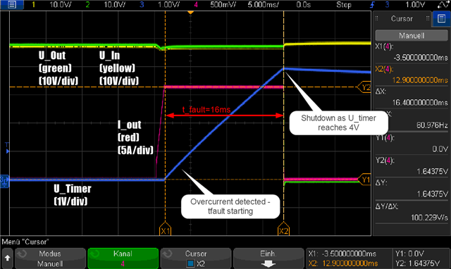
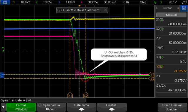
1. Successful test (as reference) - Switching off 16A - Power supply is turned on. After the U_Out has reached 48V the el. Load is activated in current-sink mode @ 16A and the circuit swiches off as intended:

A:Switch-Off succuessful @16A B:Zoom of Switch-Off

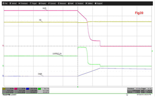
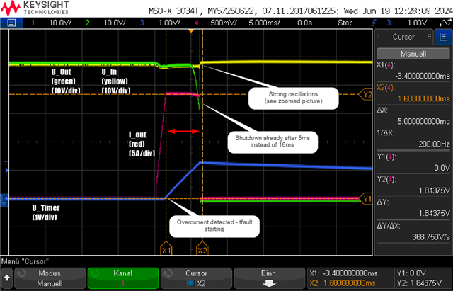
2. Failure - Switching off 18A
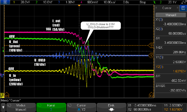
A: Switch-Off failure @18A B: Zoom of Switch-Off with U_OVLO (blue)

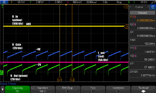
3. After the IC has shut down, there are continous repetitive voltage slopes at U_gate and Uout (while U_timer stays low on 0V). After  the el. load is swiched off, the IC seems to restart and goes back into normal operation (Q1 on and Pgd high ohmic) . In my understanding, the IC should be staying latched off.

A: Voltage slopes after faulty switch-off while el. load is still active (U_timer = constant 0V, not shown on this plot)

My first assumption was that in the second test (failure @ 18A) the device is reset by OVLO as the input touches 2.5V.  Still, this doesn't explain the strong oscillations that occur on the input and output line. Apart from that, the 2.5V OVLO-Level is reached while the IC is already swithing off, so this cant be the initial reason for switching off before U_timer has reached 4V. 

My second guess was a negative voltage level between OUT and GND(_IC) as this could reset the IC because D4s forward voltage is too high. But if we have a look at picture 1B the IC switches off successful even at voltages of -3.3V. In the failure setup i dont see the OUT voltage going lower than that.

Unfortunately, i dont know the exact impact or behaviour of the el.Load on the test setup but in my opinion the IC is supposed to keep its latch-off functionality no matter what load is attached to it.
Do you have an Idea what could be the reason for this?

  • Hi,

    I am on travel. I will get back on this by early next week

    BR,

    Rakesh

  • Hi,

    The LM5069 gate starts responding to fault after 3-4 ms and folds back the fault current to power limit value (Plim/Vds). 

    16ms is pretty long. does your design has SOA margin ?

    Why do you need such long timer period ?

    BR,

    Rakesh

  • Hi,
    the reason for the long fault-time is that we want to have a high tolerance for longer overcurrent spikes. This is considered for the MOSFET SOA and tested.

    Do you have any idea what might lead to the behaviour in picture 3?

  • e-load should be the cause for such weird behavior. Please use resistive load or your end load for evaluation.

  • TPS4811-Q1 would be good option to support such long blanking for transient loads. please have a look

  • Its working good for resistive loads and also our loads intended for application. Still, this behaviour makes me suspicious about possible design flaws and i would like to understand the root cause of this.
    I have repeated the same tests with the following changes:

    • Add Back-To-Back FET (same as Q1)
    • Remove C4 as i suspected this to inject transient negative voltage spikes into OUT
    • Pull OVLO low, so OVLO-Feature is disabled  

    -> All three didn't change the behaviour.

    A major question is: Why does the IC already switch of after 5ms in the 18A run? In my understanding this only happens when an UVLO/OVLO occurs, right? Or are there any more conditions?

  • Have you tried with shorter timer period such as 1ms or 2ms ?

  • I have tested this by changing C3:

    • C=200nf -> tfault = 9,5ms -> Fail
    • C=100nF-> tfault = 4,7ms -> O.K

    This result makes sense as in the second run with tfault=4,7ms the IC shuts down before the oscillations occur (after approx. 5ms).
    Still, this doesn't explain the root cause but rather fights the symptoms.

  • As I mentioned, LM5069 starts responding to fault after 3-4 ms and folds back the fault current to power limit value (Plim/Vds). So, we cannot use LM5069 for long fault durations.


  • Are longer fault times >10ms a general problem or only in this particular example? In my understanding the fault time should be only limited by the Mosfet SOA which in this case is capable of driving a hard short-circuit for the whole fault time.

  • Hi,

    It will be clear if we explain with results in the data sheet. 

    As you see in Figure 38, the load current is rising gradually and the LM5069 serves the load for the entire fault timer period 7ms without limiting the current.

    where as in case of Figure 39, for load current step, the GATE of LM5069 foldbacks to limit the current to power limit threshold (Plim/vds) even before timer expires.

    The same behavior is happening on your setup as well.

    It's the load current step (in other words % of load overdrive)  which is the cause for current to foldback. 

    BR,

    Rakesh

  • Hi Rakesh,
    thanks for the clarification. I dont exactly agree with the statement for Figure 38, maybe im wrong here and we can clarify this:
    In fact, the LM5069 is in current limiting mode, you just dont see it because the load current is close to the threshold -> If the load current ramp would be more steep i would expect the limiter to reduce the gate- (and output) voltage until the current threshold is reached. Meaning that the IC actively regulates the current to its threshold value by increasing the Voltage Drop over the FET DS in linear mode. Eventually the IC would switch to Plim/vds as soon the power limit threshold is reached after the Output voltage has dropped.

    On Fig39 i dont really understand whats happening in the first 3ms after the load current step. Is this some kind of a blanking time? And why is the current limited to 19A while the limit threshold is at approx. 13A?

    Fig38 FIG39
  • A call would help to clarify 

    Please share your email to send meeting invite. We can do in early next week