This thread has been locked.

If you have a related question, please click the "Ask a related question" button in the top right corner. The newly created question will be automatically linked to this question.

TPS65987DDJ: Problem with Configuring TPS65987DDJ

Part Number: TPS65987DDJ
Other Parts Discussed in Thread: TPS65981, TPS65987

Tool/software:

We used the TPS65987DDJ on our board for charging various devices, such as smartphones and laptops, We don't use flash near the chip, and we want to configure the chip using a microcontroller with I2C. However, I can't configure the chip with the 'TPS65981_2_6_7_8 Application Customization 6.1.4' application. And we configure the chip via I2C with the configuration below:

register address data len value
0x6 8 0x0
0x27 14 0x7800000014140080000900090001
0x28 5 0x1dfb658c9
0x29 4 0x40110402
0x32 64 0x190000000000000000000000000000006412c0004b12c0002d12c0101912c000000550000fc04
0x33 57 0x1900000
0x42 4 0x41a
0x47 49 0x70020027c00000000000000000000000000000000001234070020027c00c440045103
0x51 7 0xb0c1c4603
0x55 1 0x4
0x5c 64 0xa0000090008070000000000000000000000270329000000000000000000000000000000080000000000000000000000000012c007
0x73 26 0x12340451
0x77 24 0x3c0000000000000000000000000001010000000012340451

these values are default standard profile for tps65987DDH( tps65987DDJ not exist in application).

So, when we don't configure the chip, it charges a smartphone with 5V and 1A, but it doesn't work for a laptop because the laptop needs 20V. However, when we configure the chip via I2C, the charger doesn't work even for the mobile.  We connect PP_HV1 and PP_HV2 in the schematic. 

I don't know what our problem is; please guide me.

4857.schematic.pdf

  • Hi Aram,

    Are you following a reference design? Typically we only support the TPS65987DDJ if a reference design is being used, otherwise it is expected to use the 987DH or DK which should be options in the GUI. If you don't select the correct part, that very likely could be why it isn't working. If you are not working on a reference design, you might need to switch to the DK as the DJ is not an option on the 6.1.4 GUI.

    And we configure the chip via I2C with the configuration below

    Can you elaborate on what you mean by this? Are you directly writing to registers?

    Can you share the .pjt file that holds the app config generated with the GUI?

    Thanks and Regards,

    Chris

  • Hi Chris,

    Thank you for your response. Which reference design are you referring to exactly?

    Yes, we use the TPS65987DDH instead of the TPS65987DDJ in the application because the TPS65987DDJ does not exist in the application.

    Yes, we extracted raw data from the application and directly wrote it into the registers via I2C.

    Attached is the .prj file.

    tps6598ddj.pjt

    And for testing in application debug mode, we created a script to write to the register. We tried with many configurations, but none of them worked. It works with 5V, 1A, but it does not work for higher voltages needed to charge a laptop.

  • If possible, please review our board schematic because we want to send the board to production. If any changes are needed, please let me know. Please note that we have connected PP_HV1 and PP_HV2 together.

  • The reference design that inspired us is SLVUBS4A (TPS65987DJ Evaluation Module) for our own product. Please share tools or guides for configuring it.

  • Hi Aram,

    The TPS65987DJ family is only really used and supported when used in specific reference designs for notebook or pc applications. If you are not familiar with these desings and not working in this application space, you shouldn't be using this part and instead be using the 987DH or DK. That is why the GUI only has the DH and DK variants as option.

    The reference design that inspired us is SLVUBS4A (TPS65987DJ Evaluation Module) for our own product. Please share tools or guides for configuring it.

    Yeah, this is not one of the reference designs I mentioned.

    Yes, we use the TPS65987DDH instead of the TPS65987DDJ in the application because the TPS65987DDJ does not exist in the application.

    Yes, this can cause an issue. The devices are not exactly 1:1 so using the DDH image on DDJ hardware is not guaranteed to work.

    Do you have an evm you are testing with?

    Is there a reason you are not using the flash memory? Typical use would be to generate the binary file from the GUI, and load that to a SPI flash. Then, on boot, the PD controller will load the image and run on it's own. The issue with the way you are doing it is the PD will enter into a default config, and if you forget a register it may not operate properly. Also, the generated binary contains app config and patch information that fixes bugs. 

    If possible, please review our board schematic because we want to send the board to production. I

    I'll take a look but will need a couple days to review and get back to you.

    I think the main change that needs to be made is to switch over to the TPS65987DK so we can be confident it will work with the GUI. I also think you will need to use the SPI flash if you want to be able to configure the part through the GUI.

    Thanks and Regards,
    Chris

  • Hi Chris,

    Thank you for your response.
    When an IC chip is available on the Mouser website, the manufacturer should provide all necessary information for it. We have purchased the IC chip and used it on our board, but now we are unable to configure the chip.

    At this point, I expect Texas Instruments (TI) to share with us the register map and flowchart diagram specifically for the TPS65987DDJ, at the very least, along with any other information that can guide us.

    We did not use flash memory because, on our board, we have a microcontroller. According to the chip's datasheet, we should be able to change the register and configure the chip via the I2C protocol whenever we need to adjust our application.

    Best regards,

    Aram

  • Hi Aram,

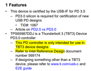
    I apologize if the device features and use case were not clear, but the TPS65987DDJ is intended for thunderbolt applications only. For TBT designs, we require that the customer is using an Intel Reference design.

    If you want access to the register map and GUI for the TPS65987DJ, you will have to request access through the link found on the TPS65987DJ product page. As mentioned before, we do require this is the TBT application and you are using a reference design, so if you do not have this information, your request will be rejected. This is the only way to get access to the documents for this device.

    https://www.ti.com/product/TPS65987DDJ

    As mentioned before, your best option is likely to switch over to the TPS65987DH or DK, which have register and GUI availability and do not require being using TBT or a reference design.

    We did not use flash memory because, on our board, we have a microcontroller. According to the chip's datasheet, we should be able to change the register and configure the chip via the I2C protocol whenever we need to adjust our application.

    Yes this is possible, but realize you will be limited to the features and operation that come default with the part. When we load an image from the SPI Flash, it loads two things. For normal use, there is an expectation to load the initial App Config and Patch code from flash memory even though it is not required.

    1: App config: Register settings set in the GUI tool so the PD controller can boot with some registers already set

    2: Patch code: Contains bug fixes and updates.


    The registers are very similar between different generations of the TPS65987, so you can use the TPS65987DH TRM as reference for the DJ if you need to do some evaluation with the TPS65987DDJ, but realize the registers may not match 100%.

    Thanks and Regards

  • Hi Chris,

    Thank you for your response.

    We have to change our chip, and we will try to do it. Fortunately, the pinout of DDJ, DDH, and DDK are the same, so we can replace it. If you have any advice for us on choosing the right chip, please let me know. Our application is only for charging smartphones, laptops, iPads, etc.

    Thank you.

    Best, Aram

  • Hi Aram,

    I would recommend the DDK, as it is the latest released and supported by the GUI. You should be able to reuse the DH resources (App notes, TRM) with the DK ic as we are still working on releasing some of the documentation to the web.

    If the documentation is a concern, then the DDH version would be the only other option.

    Thanks and Regards,

    Chris

  • Hi Chris
    thanks for your advice.

    Best

  • Hi Aram,

    Your welcome, let us know through E2E when you have the new ICs and are testing.

    Thanks and Regards,

    Chris

  • Hi Chris,

    We replaced the chip and are now using the DDH chip, but it is not working when we set the profile (DDH - standard profile - DFP) and program the profile in the TPS65987DDH (from Device -> export setting to device RAM menu). When we go to debug mode, we see that some of the settings were applied, but some were not. For example, the settings for register 0x32 (transmit source capabilities) and register 0x5C (I/O config) were not applied.

    Could you help us identify the problem? You can see our schematic in the first message in this forum, and our settings are exactly the default profile (DDH - standard profile - DFP).

    Best Aram

  • Hi Aram,

    By debug mode, do you mean the GUI Debug mode?

    Are you using an EVM or attaching directly to your board? Do you have a TIVA on your board?

    Can you save the project (project, save project) and share it with me so I can test on my end?

    I'm not very familiar with that specific GUI setting and will need to test it on an EVM on my side with your project.

    Thanks and Regards,

    Chris

  • Hi Chris 
    Yes, I mean GUI debug mode. No, we don't use EVM. We connect the GUI directly to our board, and we don't use TIVA. Instead, we use an external FTDI for communication with the TPS via I2C.

    Attached below is the project.
    TPS65987DDH.pjt

    Best

  • Hi Aram,

    Thanks for clarifying you are using the FTDI, that makes more sense. Give me some time to test with your configuration. As mentioned before, I don't see that GUI tool used often so will need to explore it more and it may take additional time.

    Thanks and Regards,

    Chris

  • Hi Aram,

    I tried using the "Export Settings to Device RAM" and have not had any success.

    When you write to the registers over I2C, do they keep the contents? If you read the register after, do they get updated?

    Unfortunately, rereading the post, I don't think the way you are trying to program the PD controller will work. I thought you were using the default configs and did not realize you also need to update source capabilities and GPIO config.

    I saw that you had a DNP'd footprint for a SPI flash. Is that something you could populate for testing? What is the reason that you want to avoid the SPI Flash?

    I took your pjt and flashed it to the SPI flash on the TPS65987DH evm and it appears to be working properly, I can soruce 5, 9, 15, and 20-V. The issue seems to be the way you are configuring the PD controller.

    To confirm the hardware works, can you test populating the SPI flash and use either the FTDI hooked up to SPI or the SPI programmer to program the GUI generated image to the SPI flash?

    I have a couple other ideas but want to check if the issue lies here first.

    Thanks and Regards,

    Chris