This thread has been locked.

If you have a related question, please click the "Ask a related question" button in the top right corner. The newly created question will be automatically linked to this question.

TPS73801: FB pin bias current

Part Number: TPS73801

Tool/software:

Hello 

In one of our boards we are using TPS73801DCQR LDO for the 5V->3.3V regulation.

In the datasheet it is mention " The value of R1 should be less than 4.17 kΩ to minimize errors in the output voltage caused by the FB pin bias current. "

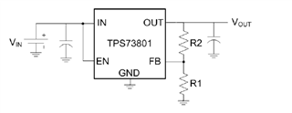
But in our design we have: R1=10K and R2=17.4K.

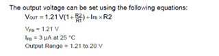
I can't understand from Vout calculation formula why R1 should be below 4.17K ?

1. What kind of problems we can encounter because we have R1=10K in our design? Please elaborate affect of this R1 on this bias issue (by my logic I thought that the greater value of R1 should be better ??).

2. Also is this TPS73801DCQR recommended for the new design (where we will initially will set R1 and R2 to the recommended values) ?

Thank you.

Alex

  • Hello Alex,

    In regards to the issue of the resistor values, the reasoning for those recommended values are to insure that the feedback current to be at 3uA. Having R1 be less then 4.17k ensures this and keeps the output relatively constant. Assuming you are going forward with this device and using 1A for your output, we recommend the listed resistor values. 

    However, I do want to help you and have you check out this new part that would facilitate your troubles. Assuming you are using 1A for your load, look at one of our newer parts TLV75733PDYDR. It  has fixed output voltages (including your 3.3V application), needs no external resistors, is smaller than TPS73801DCQR, and more cost effective.

    Hope this was helpful,

    Jorge

  • Hello

    1. What will be the affect with R1=10K (instead of resistor value below 4.17K)? Is it only higher bias current that will cause to less predictable Vout voltage value? Or there can be another negative affects for example like higher ripple (ringing) and etc.. ? I want to know if I must to change currently used feedback resistors values (R1=10 and R2=17.4K).

    2. Regarding new recommended device:

    * I need 0.5A (3,3V conversion from USB).  

    * Smaller size is not an issue in my case.

    * Thermal resistance is better in TPS73801DCQR.

    * Other parameters are better in a new suggested device.

    As we already using TPS73801DCQR there is an advantage to keep using it also in another design (to have less part numbers definitions, assembly subcontractor is already used to TPS73801DCQR and etc..). All this in relevant only if the TPS73801DCQR is not too old and not going to be soon with N.R.N.D status or a new component is much better.  

    Thank you.

    Alex

  • Hello Alex, the affects of having larger resistors would reduce the biasing current however, the FB pin has a substantial leakage current. If the feedback driver current is within one or two orders of magnitude of the FB pin leakage, it can result in an output voltage error. This is reflected here:

    Hope this as helpful,

    Jorge 

  • Hello,

    I understand that resistor values can impact the output voltage accuracy. However, with the higher resistor values I am using (R1 = 10kΩ and R2 = 17.4kΩ), are there any other potential negative effects, such as increased ripple or oscillations, etc.? I need to know if I must replace the existing resistors with resistors of the recommended values.

    Thank you.

    Alex

  • Assuming you keep the R values and meet the required cap values, you shouldn't experience any ripples/oscillations. 

  • Hello,

    I understand that using higher resistor values in the feedback network can impact the output voltage accuracy of the TPS73801DCQR LDO. Currently, I am using resistor values R1 = 10kΩ and R2 = 17.4kΩ.

    1. Beyond the output voltage accuracy, are there any other potential negative effects, such as increased ripple or oscillations, associated with R1 = 10kΩ and R2 = 17.4kΩ resistor values?
    2. If there are potential negative effects, can you specify what they might be and whether I need to replace the existing resistors with values below the recommended 4.17kΩ for R1?

    I must get clear answers to these questions as the previous response was not sufficiently detailed.

    Thank you.

    Alex

  • Hello Alex,

    Some possible negative effects of having too large off a resistor network would
    result in having a higher/lower biasing current in the FB pin.

    Having too high/low of a biasing current in the FB pin could result in the error amp outputting
    the wrong voltage. We cant guarantee if the voltage output from the error amp would be consistent
    since we don't measure or record this type of behavior. In other words, we aren't confident that the
    op amp would operate as intended or output the same voltage

    Also another thing to potentially consider is the thermal relation with having too much or not enough
    current going into the FB pin. This could affect overall performance and life expectancy of the device.

    In regards to ripples or oscillations, you should not experience any assuming your caps are sufficient.
    The device would have less Iq as a result of the large R network.

    Hope this is more than sufficient to answer your question.

    Regards,

    Jorge