This thread has been locked.

If you have a related question, please click the "Ask a related question" button in the top right corner. The newly created question will be automatically linked to this question.

TPS92691: Sometimes TPS92691 goes into a state where it stops working, even with PWM on the input.

Part Number: TPS92691

Tool/software:

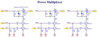
The circuit bellow is designed to blink three different LED boards, based on the Power Multiplexer circuit. The PWM and Select signals (SEL1, SEL2 and SEL3) are properly synchronized to avoid no-load operation.

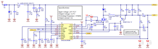
It works quite well, but sometimes TPS92691 goes into a state where it stops working, even with PWM on the input. This happens at startup or during operation. 

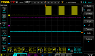
As shown in th following graph, when the PWM starts (Ch. 1), the voltage at SS pin (Ch. 3) remains high indicating that IC has not been initialized. Channel 2 shows the voltage at the OPV pin.

For the circuit to work again, it is necessary to turn off the power supply for a while.

Does any one know what could be happening?

  • Hello Caio,

    The responsible engineer for this device is not in the office today so the response to the post will be delayed.

  • Hello Calo,

    If it fails, then what happens?  Does it restart on its own.  Please have a scope capture of the output current along with GATE and VIS when it's failing.  

    Please also try changing C13 to 100nF and remove R2 to see it helps.

    Thanks Tuan

  • Hello, Tuan.

    It simply reamains in this state and does not restart. I don't have the scope capture now, but during the fault there is no pulse on the GATE and consequently no current at the ouput.

    Actually, I found the problem but I still don't know the main reason. Resistors R8 and R9 have been demaged, which causes error in current measurement. The driver IC shorted-circuit once. Maybe this demaged the resistors, right?

  • Caio,

    With normal operation, there should be no issue even with an over-current event.  It's hard for me to see how those two resistors can be damaged.

    You have circuit that is called Power Multiplex.  If this change loads during normal operation, then you can get an over current event and shuts down but it will then restart.  If you change loads during normal operation and LED's are different in forward voltages then you can have issue.  The switching of the loads needs to be done when the IC is off.

    Thansk Tuan

  • Tuan,

    I don't see how those resistors got demaged too. For some reason, the IC failed once just by being powered (without commands to activate the LEDs). When this happened, the resistor R5 was open circuited because VIN shorted to GND internally. Maybe this caused an overcurrent event in resistors R8 and R9.

    The question is: how did the IC get short-circuited just by being powered? My hypotesis is the input pi filter, which causes overvoltage during startup. In this project the nominal input voltage is 50V (12S li-ion battery). That makes sense?

  • Caio,

    I do not know how those resistors would get damaged during normal operation if VIN does not exceed the rated voltage of the TPS92682.  I do understand your thought process of the PI filter can have higher Q and the voltage can ring up.  However, it looks like you have dampening network on the filter with R4, C3 and C4.  I would place the transorb D2 after the inductor and parallel with C8.

    Thanks Tuan