This thread has been locked.

If you have a related question, please click the "Ask a related question" button in the top right corner. The newly created question will be automatically linked to this question.

TPS3897: Transient Model doesn't work properly

Part Number: TPS3897

Tool/software:

Hello experts,

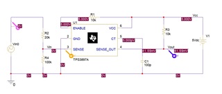
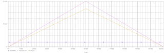
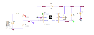
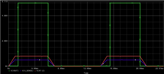
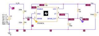
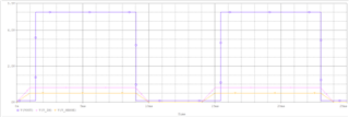
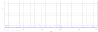
I tried simulating the TPS3897A Transient Model with PSpice for TI, but the output was not as expected. (No errors were displayed.)

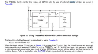
Why doesn't the SENSE_OUT change even if the SENSE exceeds 500mV?

----------

Part: TPS3897A
Date: 08/29/2011
Model Type: TRANSIENT
Simulator: PSPICE
Datasheet: SBVS172 - July 2011

Updates:
Final 1.00
Release to Web.

----------

PSpice for TI
23.1-2024 S001 Windows SPB 64-bit Edition

----------

Best regards.

Taka

  • Hi Taka.

    Thanks for your question. I'll get back to you on this by Tuesday (06/25). 

    Best,

    Sila 

  • Hello Sila,


    Have you found about this after that?


    Best regards,
    Taka

  • Hi Taka, 

    Sorry for the delayed response. I'm currently checking this issue with my team. Can you please let me know have you ever tried downloading the model and try simulating it in Pspice? 

    Best Regards,

    Sila Atalar 

  • Hi, Sila

    I don't have a license for PSpice.
    I simulated the local library (CDS_SPB_HOME\CDSSETUP\PSPTILIBDIR\TPS3897A.lib) in PSpice for TI (23.1-2024 S001 Windows SPB 64-bit Edition),and then I simulated TPS3897A Unencrypted PSpice Transient Model Package (Rev. A) (SBVM073A) downloaded from www.ti.com/product/ja-jp/, but the results were the same. (See Schematic.jpg and Result.jpg)

    Best regards,

    Taka

  • Hi Taka, 

    Thanks for pointing out this issue. I'm not sure what is causing the model behave this way but I'm also seeing similar behavior. This is an older device and model should be working.

    I'm checking with my team but I may need more time to provide some feedback. 

    Best

    Sila A 

  • Hi, Sila

    Thank you for your reply.
    I understand the situation. I am looking forward to hearing from you again.

    Best regards,

    Taka

  • Hi Taka,

    Thank you for your understanding! I noticed the model is working when there is a dc source that higher than the sense threshold voltage at the SENSE pin. I think best way to support you with this inquiry is providing a oscilloscope picture that shows the expected behavior of your design.

    I will provide that scope picture by the end of this week. 

    Best Regards,

    Sila 

  • Hi Taka, 

    I found the issue and it is not the model. Please increase the resistor divider (R2 an R4) at the Sense pin. Please find my simulation result and schematic in below. 

    Please find the relevant information regarding resistor divider in the datasheet in section 8.3.1 Input Pin (SENSE).  The resistor values needs to be higher than 100k. 

    I hope this helps! Please let me know if it doesn't work. 

    Best Regards,

    Sila Atalar

  • Hi, Sila

    Thank you for your support.
    I simulated the model based on your information
    and it seems to work only when V_IN=(1+R1/R2)*0.5,
    but not when V_IN>(1+R1/R2)*0.5.


    Does this behavior meet the specifications of this model?

    Best regards,

    Taka

  • Hello,

    Due to the US holidays, our team will respond back the week of July 7th.

    Thank you for your patience.

  • Hi Taka, 

    Sorry for the delayed response and thanks for your patience. 

    I want to let you know that I got the same reset behavior from the simulation. It seems like there is something wrong with the model, it is not fully showing the output behavior.  Our team is already start working on this. Once again, thanks for bringing that to our attention!

    I used the TPS3897A-6P-EVM047 evaluation module (EVM) to provide you the expected behavior. 

     In the above oscilloscope picture, Vsense (3.2V) is applied to resistor divider so that the voltage at the SENSE pin is equal to 0.5V  ( there is no test point to monitor the voltage at the sense pin on the EVM board).  As you can see it here, the reset is asserted after the reset delay.

     In the above oscilloscope picture, Vsense (5V) is applied to resistor divider so that the voltage at the SENSE pin is equal to 0.8V and the reset is again asserted after the reset delay. 

  • Hi Sila,

    Thank you for your support.
    I understand that TPS3897A-6P-EVM047 works as expected.
    Please let me know if you find any problems with the model.

    Best regards,

    Taka