This thread has been locked.

If you have a related question, please click the "Ask a related question" button in the top right corner. The newly created question will be automatically linked to this question.

TPS25942A: TPS25942

Part Number: TPS25942A

Tool/software:

Dear team

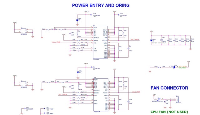
We are  using TPS25942 based active power oring circuit for our custom with power requirementof 12V @5A.

when we powering on our bord, some times our oring IC TPS25942 is getting damaged. As per datasheet mosfet should off during high load condition.

could you please suggest why this IC is getting damaged.

attaching schematic for your reference.

  • Hi Krishnam,

    Can you please answer the following

    • Any visible damage to ICs? If yes, then which pin? 
    • Is this damage happening consistently or it happens sometimes only.
    • What is the load condition. How much current is being drawn when the damage was seen
    • Any tests performed or damage is seen during first startup itself. 
    • Any waveforms?

    Best Regards,
    Arush

  • Dear Arush

    Thank you for your reply.

    1. There is no physical damge on the IC but it is not working.

    2. Our board is taking initial surge during the booting, looks like which is more than 5.2A

    3. After that both oring ICs are not working. We bypassed complete load and checked. (After replacing with new oring ICs with out load oring is working fine.)

    4. Same thing we checked with the extranal DC load also(Bypassing our card load). Oring is working fine till 5A laod. When we are giving more than 5.5A load, IC stopped working. After reducing load to 3A it is not coming back to normal . 

    When we are giving over load at one IC input, Other IC also not working(When we tried with normal load).

    When we replace both the ICs, they are working with the normal load(<5A).

    As per data sheet FET should be turned off and should work when load is normal. Is it correct? Other wise at every over load we need to replace IC?Power oring.pdf

    Please check. Waiting for your valuable reply.

    We designed Oring for 12V @5A load.(Both inputs are of 12V)

    With Regards

    Krishnam Raju M

  • Dear Krishnam Raju M,

    It looks like the ILIM is set to 5A and Fast trip level will be 7.87A.

    Same thing we checked with the extranal DC load also(Bypassing our card load). Oring is working fine till 5A laod. When we are giving more than 5.5A load, IC stopped working. After reducing load to 3A it is not coming back to normal . 

    Are they getting damaged or coming back after power cycle? 

    Again, can you share waveforms. Do you have surge profile or transient values? How much current is load drawing during startup and is it possible to turn on the ORing device and then connect the load (sequential startup of the system)

    What is the part number of input side diode?

    Best Regards,
    Arush

  • Dear Arush

    Thank you for your immediate reply.

    Our requirement is also for 5A. 

    1. Yesterday at one time , We wantedly applied more load 5.7A through electronic DC load. This IC was physically damaged. Other Oring IC also stopped working, for which the physical look is good.

    2. Remaining most of the time ICs are physically good not coming back after power cycle( With our board load).

    3. We are debugging the reason for our board surge/transient issues and will update.(We will try to provide our surge load details)

    4. Presently we are not mounting the input diode.

    Please clarify the below

    5. If the load is less than 5.7A , It should recover after a new power cycle. Is this correct?

    We are using TPS25942A, Which will try to auto recover. 

    6. Is it mandatory to provide PGTH as 1V. right now we are giving 6V, As R44 and R520 both are having the same value.

    With Regards

    Krishnam raju M

  • Hi!

    I apologies for delayed response. Thank you for your patience.

    6. Is it mandatory to provide PGTH as 1V. right now we are giving 6V, As R44 and R520 both are having the same value.

    If you are not using PG signal, then you don't have to worry about it. For this device 6V is also fine. Internally there is a comparator with 0.99V as threshold. any value above the threshold but less than recommended max of 18V is fine. 

    5. If the load is less than 5.7A , It should recover after a new power cycle. Is this correct?

    Since the ILIM is set to 5A, during the overload event like 5.7A, the device will regulate the current to 5A and will dissipate the excess power. This power dissipation can cause junction temperature to rise up and cause Thermal shutdown. This TSD can recover after power cycle or auto-retry will also recover from this. During current regulation, FET is still on and there is no fault, so the device doesn't require power cycle. 

    4. Presently we are not mounting the input diode.

    TVS diode at input can prevent device from getting damage. Voltage above the abs max will cause damage (external or internal) to the device.

    Best Regards,
    Arush

  • Dear Arush

    Thank you.

    With Regards

    Krishnam Raju M

  • Dear Arush, 

    Thank you for your valuable support. I wanted to ask one more question about my power circuit.

    1. After Power oring with TPS25942, 12V is going to my 2 buck regulators(LTC7151S). One buck is used for the processor core(1V) and this regulator is going bad frequently.

    Sometimes the 3V3 regulator also goes bad(attached power tree).

    2. Initially we are seeing voltage drop and after that this buck regulator is going bad and  input and output voltage points impedance short were found (Input to ground and output to ground impedance was fine).

    3. We found some times these regulators are going bad when we touch accidentally also.

    4. In some boards these regulators are fine.

    Could you please analyse the issue and what could be the possible reason?power tree.pdf

    With Regards

    krishnam raju m