This thread has been locked.

If you have a related question, please click the "Ask a related question" button in the top right corner. The newly created question will be automatically linked to this question.

UCC24624: REG maximum driving capability current for parallel connected MOSFET

Part Number: UCC24624

Tool/software:

Dear Team,

Thank you for all the help and support.

We are planning to use UCC24624 in LLC converter for driving secondary side synchronous MOSFETs (which will be parallel connected for current sharing). We have below questions related to it:-

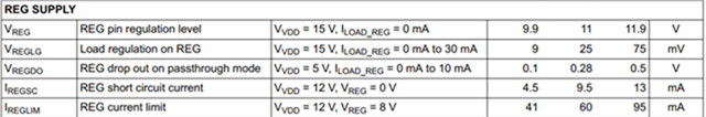
1) What is the maximum current (average) which can be taken from REG for driving MOSFETs?  Is it 30mA with a drop of around 75 mV on the REG voltage of around 10V? Does the IREGLIM parameter mean if we take 60mA current from REG supply, the REG voltage will drop from 10V to 8V?  

2) If we go with two UCC24624 controller for driving the parallel MOSFET, the configuration shown in below figure 1 (screenshot taken from Configs of Secondary Rectifier Circuit for LLC Resonant Converter Using UCC24624 ) The document suggests to put two more windings to sense drain to source voltage of the MOSFETs. Configuration for  second UCC24624 in figure 1 seems to be incorrect, drain voltage of S3/S4 MOSFET is sensed from Vd2 and gate voltage is applied from Vg1.

Further, We dont want to put two more windings , so we are planning the configuration shown in figure 2 below. Will the planned configuration of figure 2 work ?


3) Is it possible to use external gate driver IC between Vg1/Vg2 of UCC24624 and Gate of MOSFET. Will the UCC24624 be able to drive gate driver IC for the entire ON duration of the SR MOSFET, keeping in mind the tMGPU time (minimum gate pullup time) of 275 nsec (typical). After that 200uA current source may not be able to keep the external gate driver's output as high. 

4) Is there any maximum power dissipation rating for UCC24624 or the maximum power dissipation is only limited by TJmax?


  • Hello Ajit, 

    Thank you for your interest in the UCC24624 dual SR controller.

    For item 1) The Min, Max, and Typ specifications given in the Electrical Characteristics table of the datasheet are based on the Test Conditions imposed on the controller.
    Although actual operating conditions may differ from the specific test conditions, the limits listed provide guidance as to the expectations for the actual conditions. 
    I expect that IREGLIM is about as much current as you can get from REG, anticipating approximately a 4-V drop in REG voltage at that current level.   
    Whereas, if you load REG to 30mA, you may expect less than 75mV drop. 

    For item 2)  I agree with you that Figure 2-3 of the "Configurations..." document (your Figure 1, above) appears to be incorrectly drawn.  The winding connections do not make sense to me.  I think it is a mistake.  I think that the configuration shown in your Figure 2, above, should work.   

    For item 3)  Yes, the UCC24624 VGx outputs can drive a gate-driver IC or buffer circuit instead of driving large MOSFETs directly. Usually the input loading on gate-driver ICs is very light and should not overload the 200uA output.   Be sure to chose a driver with very low propagation delay.  

    For item 4) Maximum power dissipation is only limited by TJmax with suitable design margin added.  

    Regards,
    Ulrich