Other Parts Discussed in Thread: TPS65982, TPS552882, TPS55288
Tool/software:
Hello,
I am designing 100W USB PD source. I want to use Buck-Boost controller TPS552882RPMR and TPS65987D as TCPC. TPS65987D will be configure via SPI memory. My config will be: UFP, Source, 100W max.
My questions are:
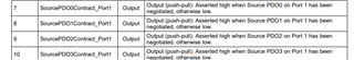
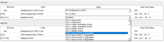
1. Best solution how to control EN pin of Buck-Boost. Can I use PlugEvent_Port1 which I mapped to one of GPIO port and it will control the enable (EN) of Buck-Boost? Is it good solution? Or do you recommend me something different?
2. In evaluation boards there is no notes about input EMI or output EMI filters for USB PD source solution. Do you recommend to use it? If yes, could you provide me some example?
3. I want to use only PP_HV1 internal switch. Is it necessary needed to connect together VBUS1 and VBUS2 pins or when I want to use only PP_HV1 I can only need to connect VBUS1 to USB-C connector?
4. Everything what is need for successful configuration of TPS65987D is use to TPS65982 Configuration Tool, generate binary and than flash the binary to SPI memory?
5. I am not sure if I understand this well.... Can I connect MCU(STM32 as i2c master) to I2C1 of TPS65987D and than read information (status information) from TPS65987D?
6. I don't want to use/support BC1.2 charging thought my USB-C port. So, I don't want to connect usb2 D+ and D- to TPS65987D. Is it ok? Can I leave pins 50 and 53 unconnected?
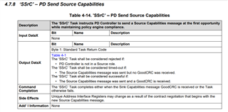
7. I want to ask if it is possible to set this event via the TPS65982 Configuration Tool. Standard setup capability for my USB PD source is 20V/5A - 100W max. When I will using battery for powering my USB PD source, I want to reduce max power to 60W. How can I do this? How to setup this in TPS65982 Configuration Tool? Idea... I am able to send high/low signal from MCU to some GPIO pin of TPS65987D which will indicate that it wants to switch from 100W max to 60W max.
Thank you
Best regards,
Martin