This thread has been locked.

If you have a related question, please click the "Ask a related question" button in the top right corner. The newly created question will be automatically linked to this question.

TPS4811-Q1: TPS4811 - OCP/SCP with PWM control

Part Number: TPS4811-Q1
Other Parts Discussed in Thread: TPS48110Q1EVM,

Tool/software:

Hello,

My application:

  • 60V input
  • 2A OCP with 2.25A SCP (fast, ~uS reponse time, latching)
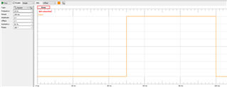
  • 200hz PWM control, high side switched

I have purchased the tps48110Q1EVM and modified the board for operation up to 60V by changing the OV/UVLO resistor ladder. I have also configured the EVM for latching CB functionality. I have not replaced the 500uΩ current sense resistor or 5A trip set resistor. The EVM works great, and the TPS48110 seems suitable as a fast response eFuse when operated at 100% duty. It also works well as a high side PWM driver.

However, during a OCP/SCP event, with PWM toggling the input pin, the device does not trip. It seems like the toggling of the input pin prevents it from acknowledging any faults, even in a dead short event.

Previously I was using the TPS1663x eFuse device, but I like how this device reacts and shuts off power in uS time. My ideal situation would be this device is acting as both my eFuse and high side PWM driver. Is there any way to modify the configuration of the device so it does trip, or external circuitry I can add?

  • Hi Phil,

    Welcome to E2E!

    However, during a OCP/SCP event, with PWM toggling the input pin, the device does not trip. It seems like the toggling of the input pin prevents it from acknowledging any faults, even in a dead short event.

    Rakesh-> Can you please share test waveforms of INP, GATE, power path current, VOUT, TMR and FLT_I/ nets to understand the issue.

    BR,

    Rakesh

  • Hi Rakesh,

    Above is the schematic. Ignore the comments about the 12.5mΩ current sense resistor and 51kΩ OCP resistor, these values have not been changed. The board is configured for the 5A trip setting.

    This is the input waveform into the INP/ test point, a 10Hz 50% duty 0-4V square wave.

    This waveform shows the Vout in orange and the fault test point in blue.

    The board is driving only a 51Ω power resistor. I did not capture power path current, but it can be extrapolated from the Vout. I am shorting the directly across the output of the EVM using an insulated screwdriver. For this capture, the screwdriver was shorted and held against the terminals for a sustained short, and continuous arcing was visible from the terminal to the screwdriver.

    ========

    For my 100% duty cycle test, no connection was made to the INP/ testpoint, so the device is kept in 100% on by the built-in input pullup. In this case, the output was shorted by a 5V TVS diode, and the orange Vout and blue FLT traces can be seen to quickly decay.

  • Hi Phil,

    thanks for the details.

    What is the difference between shorting methods in both cases ? if there is - can you try with same shorting approach ?

    the shorting path takes current from Vin.. so, we cannot interpret exactly the current from Vout

    Is Vin going below UVLO threshold for the 1st case ?

    BR,

    Rakesh

  • Hi Rakesh,

    I have tried the same shorting methods for both cases, and in both cases when the TPS4811 has been driven with an input signal, it seems to not obey current limitations.

    In the related post, you said

    "TPS4811-Q1 can do PWM switching but it does not limit the current in the path"

    Does this mean the TPS4811 does not current limit when in PWM mode through the input pin? If so I assume this is the source of the issue.

  • Hi Phil,

    yes.. TPS4811-Q1 does not do current limiting 

    BR,

    Rakesh