Tool/software:
Hello, I have designed an IEPE excitation source current and differential amplification circuit based on the TI-010249 four-channel synchronous vibration sensor interface reference design;
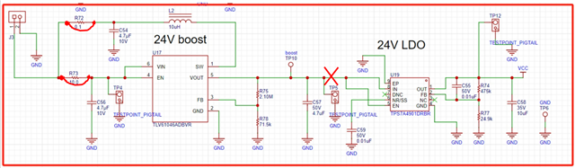
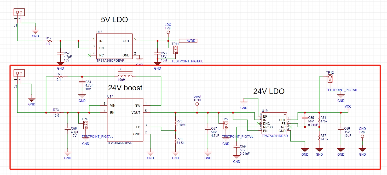
The circuit diagram of my design is as follows:

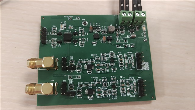
The physical drawing after I punched the board is as follows (I punched two PCB boards):
After I received the boards, I accessed J1 J3, 5.2V DC respectively; it showed the following phenomenon:
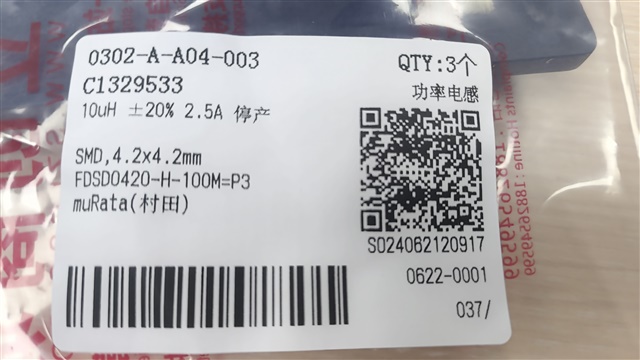
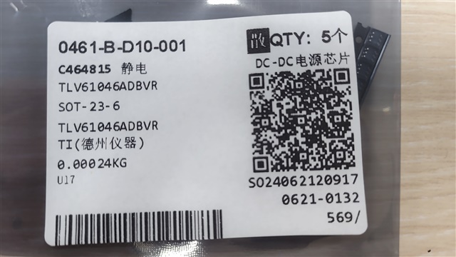
Inductor L2 there is whistling, U17 white smoke; after a while I measured the measurement points:
1. J1 input 5.2V, TP11 (AVDD) is 5.01V, LED2 normal light; (all normal)
2. J3 input 5.2v.
The first board TP4 is normal, same voltage as my input; TP5 is 12V; TP12 is 12V; both are transformed values, seems to be the same value;
The second board TP4 is normal, the same voltage as my input; TP5 is 5~8V (transformed value); TP12 is about 2.78 (sometimes 2.54) V; there is also a slight "squeak" sound when it is powered on. 3;
3. according to the reference design, it should output a clean 23.8V;
I think the problem is in this boost circuit: maybe U17 U16 L2 are faulty?
But I'm not sure if it's the schematic I designed that's wrong? Or is it my device selection? Or is it a problem with the soldering? Or something else?
Schematic design: I would like to ask you to reconfirm the circuit diagram above;
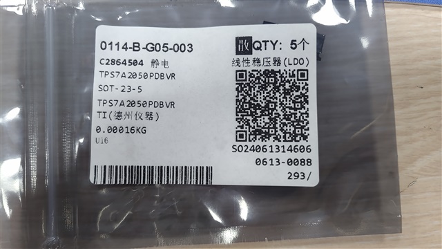
In terms of device selection: I have selected capacitors and resistors according to the device models provided in the reference design, and inductors and op-amps are selected as follows:
Soldering: I have checked the resistors and capacitors on this circuit, and there is no mislabeling of the devices; the solder joints also all look fine;
So I would like you to help me research where the problem is and how to fix it?
Altium_0608_IEPE++_2024-06-20.zip
Thank you very much!