This thread has been locked.

If you have a related question, please click the "Ask a related question" button in the top right corner. The newly created question will be automatically linked to this question.

LM2621: Set up sample application for testing. Current with enable pin set to GND causing ~50uA instead of expected 2.5uA

Part Number: LM2621

Tool/software:

Hi Guys,

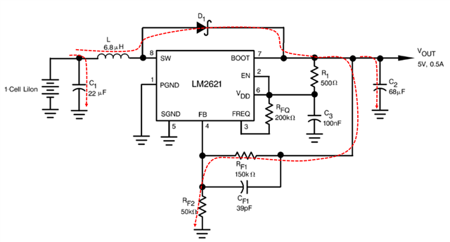
Set up the sample circuit breadboard style from the datasheet (Figure 13). All components used were following the schematic aside from RF1 and RF2 (100K and 22.2K). 

Input Voltage: 5V 

Output Voltage: ~7V


When completed the enable pin is pulled to GND (should be in sleep). I noticed that the current draw is around 50uA. According to the datasheet it should be 2.5uA. 

At a loss of what could be causing a higher current draw than specified. Curious if anyone has any insight that could aid me forward. Curious if a component or a wire that is longer than ideal could be causing such issues with current or signal. 

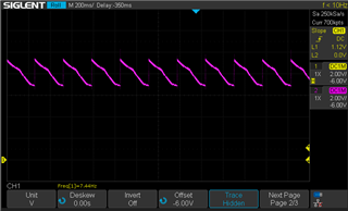
Also noted that when the enable pin is set to high, the sawtooth signal is slow until a load is present. Am curious if this is expected behavior. Please see attached image. 

Any help would be much appreciated! 

  • Hi Jimmy,

    Let me check and get feedback to you tomorrow.

    Regards

    Lei

  • Hi Jimmy,

    In your setup, there will be additional leakages from the path of inductor --> diode --> RF1 --> RF2 --> GND (the major part) and from the input and output capacitors. These leakage are not counted in the max 2.5μA leakage in datasheet.

    What's the sawtooth signal? Vout? And what's the voltage for each div in the picture?

    You may type in ChineseGrinning

    Regards

    Lei

  • Hi Lei, 

    Thank you very much for your quick response. Would you have any insight on how to decrease the leakage current from those components? 

    For the signal output the max and minimum Vout on the sawtooth signal is 9.4V and 7V with a 2V per div. For the time, it is a 200ms per division. 

    Thank you! 

    Jimmy 

  • Hi Jimmy,

    how to decrease the leakage current from those components

    The leakage from the path of inductor --> diode --> RF1 --> RF2 --> GND is decided by the topology. The only way of reducing this leakage is to increase the RF1 and RF2 simultaneously, for example, RF2 = 100kΩ and RF1 = 300kΩ. Please note that if RF1 and RF2 are too large, the Vout DC accuracy may decrease slightly. And also, as the RF1 increases, please decrease the CF1 proportionally to make the RF1*CF1 as constant.

    For the signal output the max and minimum Vout on the sawtooth signal is 9.4V and 7V with a 2V per div

    This is abnormal. The Vout should be very stable without such a big ripple. 

    Please check whether the 68μF output cap(C2) is correct. And what's the Iout during your measurement?

    Regards

    Lei

  • Hi Lei, 

    Thank you for your swift response. I will look into modifying the resistor and capacitor values to see if I can decrease the leakage current. 

    Regarding the Vout, I have the enable pin connected to a 2pos switch. One position to GND and the other to Vin. I noticed that when the EN is connected to GND the Vout is equal to Vin. When EN is connected to 5V Vin, the Vout is the sawtooth signal shown in the image previously sent. However, when the EN pin is left floating the output is stable with minimum ripple. 

    When the EN pin is connected to Pin 6 node like in the datasheet, I still receive a sawtooth signal but with a shorter tooth amplitude. Would you have an explanation for this? 

    For C2 I am using the T495C686M016ATE250 (CAP TANT 68UF 20% 16V 2313. 

    When measuring the signal, Iout is connected to a device that pulls just a few uA. When a higher load is presented the signal is more stable. 

    Thank you for your help, 

    Jimmy 

  • Hi Jimmy,

    when the EN is connected to GND the Vout is equal to Vin

    It is normal. Because when the LM2621 is disabled, the Vout equals to the Vin if ignored the voltage drops on inductor and diode.

    When EN is connected to 5V Vin, the Vout is the sawtooth signal shown in the image previously sent. However, when the EN pin is left floating the output is stable with minimum ripple

    It's quite abnormal. We can find out the reason here first then check your second question.

    Could you help double confirm that when the 2pos switch switches to 5V, is the voltage on EN pin a stable 5V?

    Regards

    Lei 

  • Hi Lei, 

    Thank you for the response. Sorry some things got side tracked for a bit. 

    I am at a loss for the issue that I am seeing as well. I'm currently working on a board to test this circuit on as it looks like I am having a lot of issues with my hand made circuit. 

    Regarding your last question, that is correct. The EN pin is connected to the 5V input of a lab bench power supply. I have not been able to get a stable on voltage yet. 

    Thank you, 

    Jimmy 

  • Hi Jimmy,

    Yes as you said, the hand made boost circuit on breadboard usually has lots of strange issues.

    Hope the new made board will work well.

    If you are OK, I'd like to close this E2E thread first. You can further reply here or open a new thread if you still have issues on the board.

    Regards

    Lei