BQ25750EVM: Does BQ25750EVM board supports the charging of 54.6V battery?

Part Number: BQ25750EVM
Other Parts Discussed in Thread: BQ25750, BQ25756, , EV2400, BQSTUDIO

Tool/software:

Hi TI Team,

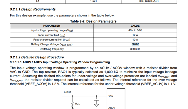
We are planning to use BQ25750 as battery charger. The requirement is specified below.

Input DC Voltage : 48V to 55V
Nominal Voltage: 49V
Ouptut Voltage:54.6V
End of Charging of Battery: 54.6V
Charging Current (max) : 3A

We are not planing to use the reverse mode as of now. 

Is the BQ25750EVM board capable of supporting the above requirement? 

  • Hello Ashfaaq,

    Yes, the BQ25750EVM can support the above requirements. You'll have to change the voltage feedback divider on FB to get the right battery charge voltage. You can use the BQ25756 design calculator to help with the calculation of the FB voltage divider.

    Best Regards,
    Ethan Galloway

  • Hi Ethan,

    While using battery of 54.6V, which is a higher voltage. Do I need any external circuity/protection circuit?

  • Hi Ethan,

    I have changed the feedback resistors Rtop = 249K Rbot=7.32K (of BQ25750EVM), for the output voltage of 54.16V.
    The Vout is generated initially, and after connecting the Battery(43V), the charger IC is not working and ACUV, ACP,ACN,SRN,SRP, these pins are shorted to gnd.

    Also Is there any test results available for higher voltages, Since the design procedure in the datasheet is mentioned for 58.8V, Are the test results available.


    Note: We have supplied Vin only after connecting the battery.

  • Hello Ashfaaq,

    While using battery of 54.6V, which is a higher voltage. Do I need any external circuity/protection circuit?

    You do not need any external protection circuitry.

    I have a few questions for to clarify this situation and help us debug this.

    The Vout is generated initially

    Can you clarify what you mean by this?

    the charger IC is not working and ACUV, ACP,ACN,SRN,SRP, these pins are shorted to gnd

    SRN and SRP are 0V while the battery is connected to the EVM? These pins should be the battery voltage

    Does I2C on the EVM function? Can you send me a log of the EVM registers?

    Yes, we do have test results for high voltages. What type of tests do you want to see?

    Best Regards,
    Ethan Galloway

  • Dear Ethan,

    The Vout is generated initially. Can you clarify what you mean by this?

    -- Prior to connecting the battery, I have verified the Output Voltage at No Load condition at J3. Then I have turned off the deivce and connected the discharged batttery(43V) to check the charging operation.
    After Powering On, The IC has got damaged.

    SRN and SRP are 0V while the battery is connected to the EVM? These pins should be the battery voltage

    --I have removed the battery and checked the impedance, and observed that SRP, SRN and ACUV are shorted.

    Does I2C on the EVM function? Can you send me a log of the EVM registers?

    --
    I am unable to read the registers using EV2400, It shows Device ACK error.

    Yes, we do have test results for high voltages. What type of tests do you want to see?
    -- Please share available test data for voltage greater than or equal to 55V. 

  • Hello Ashfaaq,

    Thanks for being patient with this. We are very busy right now and I'll get back to you later this week.

    Best Regards,
    Ethan Galloway

  • Hello Ashfaaq,

    We are still looking into this. Can you get a few pieces of data for me?

    Can you look at the FETs on the EVM and tell me the part number of the FET?

    Can you also measure the resistance of R22 and R25?

    Best Regards,
    Ethan Galloway

  • Hi Ethan,

    Please find the details below.

    Q1,Q2,Q3,Q4 - AONS66920
    Q5,Q6,Q7,Q8 - AONS66917

    The value of R22 & R25 is 10 ohm.


  • Hello Ashfaaq,

    Thanks for the new information.

    I'll get back to you later on this week.

    Best Regards,
    Ethan Galloway

  • Hi Ethan,

    ,May you please assist here?

  • Hello Ashfaaq,

    Thanks for being patient here. I'll get back to you tomorrow.

    Best Regards,
    Ethan Galloway

  • Hi Ethan,

    We have replaced the BQ25750 IC in the EVM board. Now there is no short observed on the ACUV, ACP,ACN,SRN & SRP pins.

    Also It would be helpful if you can share the register configuration file.

    I have followed the steps provided in the User Guide. But Output voltage is not generated.

    In my board, Fb R64 is replaced with 7.32K for 54V Output. I haven't changed anything else.I have Set /CE to low using JP13. Also jumper is connected between pin 1&2 of JP12.  JP 1, 4, 5, 6, 9, 10, 16 is mounted.

    I would like to ensure the generation of Stable Vout(54.6V) prior connecting the Battery.  Hence I am validating without the Battery first.

    Vin range - 39V to 54.6V/ 6A,  Vout=54/2A. but Vout is not generated. 

    Requesting your assistance on the same.


  • Hello Ashfaaq,

    Thanks for working with this. I've got a few questions: Does I2C work on the IC? What state does the IC report and can you send me the register file?

    I think the only change you'll need to make is to disable the watchdog timer and set charge current ICHG to the correct value.

    Best Regards,
    Ethan Galloway

  • Hi Ethan,

    Yes I2C is working fine.
    Please find the register file below. Initially we have tried by disabling the watchdog time and Ichg=20A, But the Vout is not generated.Hence we tried to change the settings as per the EVM guide again. The below file might have some error in configuration. Please help us configuring the same. 

    Vout 54V /2A. Firstly, I would like to check the Vout without connecting the battery

    Requesting your prompt response.

    Bq25750_Reg_Config.txt
    * Created: Sat Jul 20 12:31:46 IST 2024
    *
    * Format: Register Name  tab Character,\t  Register Address  tab Character,\t  Hexadecimal register value.
    * BQZ Container: Charger_1_00-bq25750.bqz
    *
    Charge Voltage Limit	00	10
    Charge Current Limit	02	140
    Input Current DPM Limit	06	640
    Input Voltage DPM Limit	08	348
    Reverse Mode Input Current Limit	0A	640
    Reverse Mode System Voltage Limit	0C	3E8
    Precharge Current Limit	10	140
    Termination Current Limit	12	A0
    Precharge and Termination Control	14	0F
    Timer Control	15	0D
    Three-Stage Charge Control	16	01
    Charger Control	17	C9
    Pin Control	18	C0
    Power Path and Reverse Mode Control	19	20
    MPPT Control	1A	00
    TS Charging Threshold Control	1B	92
    TS Charging Region Behavior Control	1C	17
    TS Reverse Mode Threshold Control	1D	40
    Reverse Undervoltage Control	1E	00
    VAC Max Power Point Detected	1F	00
    Charger Status 1	21	01
    Charger Status 2	22	80
    Charger Status 3	23	02
    Fault Status	24	00
    Charger Flag 1	25	00
    Charger Flag 2	26	00
    Fault Flag	27	00
    Charger Mask 1	28	00
    Charger Mask 2	29	00
    Fault Mask	2A	00
    ADC Control	2B	20
    ADC Channel Control	2C	02
    IAC ADC - Use Field View	2D	00
    IBAT ADC - Use Field View	2F	00
    VAC ADC	31	00
    VBAT ADC	33	00
    VSYS ADC	35	00
    TS ADC	37	00
    VFB ADC	39	00
    Gate Driver Strength Control	3B	00
    Gate Driver Dead Time Control	3C	00
    Part Information	3D	02
    GM Adjust	61	30
    Reverse Mode Battery Discharge Current	62	02


    Additionally, Please find the yellow highlighted VOUTReg option is not available for me.


    Below is from our EVK board.


  • Hi Ethan,

    Please assist. Our product deliveries are getting delayed.

    Thanks in Advance !

  • Hello Ashfaaq,

    Thanks for being patient with this. I think the IC may be stuck in trickle charge mode. Is it possible for you to run a few tests for me?

    If you set EN_PRECHG=0, does the IC work as expected? I would recommend setting ICHG=0.4A while running this test. I also recommend plugging the battery in first, disabling the charge, and then plugging in VAC before starting the test.

    Also for your VIN range of - 39V to 54.6V. I would recommend a diode to prevent the reverse voltage. -39V might conduct through the body diodes of the switching FETs.

    Can you try to replace the IC on the board to see if that makes a difference?

    Best Regards,
    Ethan Galloway

  • Hi Ethan,

    Thanks for the input. I have tried  EN_PRECHG=0 and ICHG=0.4A, but Voltage is not geneated.

    I will also try to replace the IC.

    Meanwhile, May you please share the test results of the 58.8V?  Also Kindly share the register config file that you have used.
    It would be really helpful.

    Thanks in Advance !

  • Hello Ashfaaq,

    Can you also try to check the FETs on the EVM and see if the FETs are good?

    Here's an example of an efficiency test we did with the BQ25750 The test is VIN=48V and VBAT=54.2V:

    For the initial testing register settings, I would recommend setting Watchdog=disabled, EN_PFM=0, EN_TERM=0, ICHG=400mA, and EN_CHG=0. Set EN_CHG=1 once you are ready to start charging and the battery is plugged into the EVM

    Best Regards,
    Ethan Galloway

  • Hi Ethan,

    I have tried the same its not working.Watchdog=disabled, EN_PFM=0, EN_TERM=0, ICHG=400mA, and EN_CHG=0 and  I have connected the battery, then plugged the Input and made EN_CHG=1,Please share the register configurations.

    All the FETs are fine I have checked it.

    Please share register configuration file. 

  • Hello Ashfaaq,

    The settings I shared are the register configurations. It sounds like either the IC or the board itself is not working. You already replaced the IC so I think the board itself is not working.

    By the way about the bqz file, the EVM User's Guide was made with an older version of BQStudio. I am currently updating this.

    I'm looking into this and I'll get back to you by the end of the week. In the meantime, do you have another EVM you can perform an ABA swap with? No problem if you don't have another EVM.

    Best Regards,
    Ethan Galloway

  • Hi Ethan,

    The settings I shared are the register configurations. It sounds like either the IC or the board itself is not working
    -- I can write the registers and able to read it again to verify the same using EV2400. So I2C is fine. And device is also responding properly.

    I am reverting back the EVM to 29V from 54, by replacing the Fb resisitor to check the operation at default condition as received.

    Please share the updated user mannual or register configuration file at the earliest.

  • Hello Ashfaaq,

    Thanks for being patient with this. I am investigating this scenario and I will get back to you next week.

    For your board, I think something is broken on the EVM. If have time to do more tests on your side, can you measure R22, R25, R5, and R6? You might also want to check the status and flags of the EVM while EN_CHG=1.

    Best Regards,
    Ethan Galloway

  • Hi Ethan, 

    These are R22, R25, R5, R6 are 10 ohm. and When EN_CHG=1, Charging status shows not charging.

  • Hello Ashfaaq,

    Thanks for the new information.

    I'm still investigating this scenario in the lab.

    Best Regards,
    Ethan Galloway

  • Hi Ethan,

    Is there any update here?

  • Hello Ashfaaq,

    Thanks for being patient with this. We are still investigating this in the lab.

    Best Regards,
    Ethan Galloway

  • Hi Ethan,

    May you please assist here?

  • Hello Ashfaaq,

    I'm sorry to keep you waiting like this. Thanks for being patient. I'm still working on this in the lab.

    There are few tests that you could to diagnose the EVM on your side.

    When set VBAT=10V and VAC=0V, do the BATFETs turn ON and you see 10V at VSYS? Conversely, when you set VAC=10V, VBAT=0V and unplug JP13, do see 10V at VSYS?

    These will tests will indicate whether or not the ACFETs or BATFETs have been damaged.

    If the ACFETs and BATFETs are good, that may indicate Q1-Q4 are bad and need to be replaced.

    Best Regards,
    Ethan Galloway

  • Hi Ethan,

    Thanks for your response. I will perform the test case and share you the results.

    Additionally, after changing the ICs and powering on the Vin at 48V, We can able to observe the generation of 54V at Vbat, also charging and discharging of caps were observed.( I have tested without Battery). 

    But the moment I turned off VIN, I heard a tick sound and now the IC got damaged but FETs are fine as usual. Status LEDs were not glowing. But 3.3V from the LDO is fine.  We have been hearing this Slight tick sound everytime at 54V Vout. This was the fourth IC. After this there was no output observed. The IC is not responding to the I2C communiction.

    The above was our observation so far, also I will perform the above and share the results with you as soon as possible.

    Thanks