Tool/software:
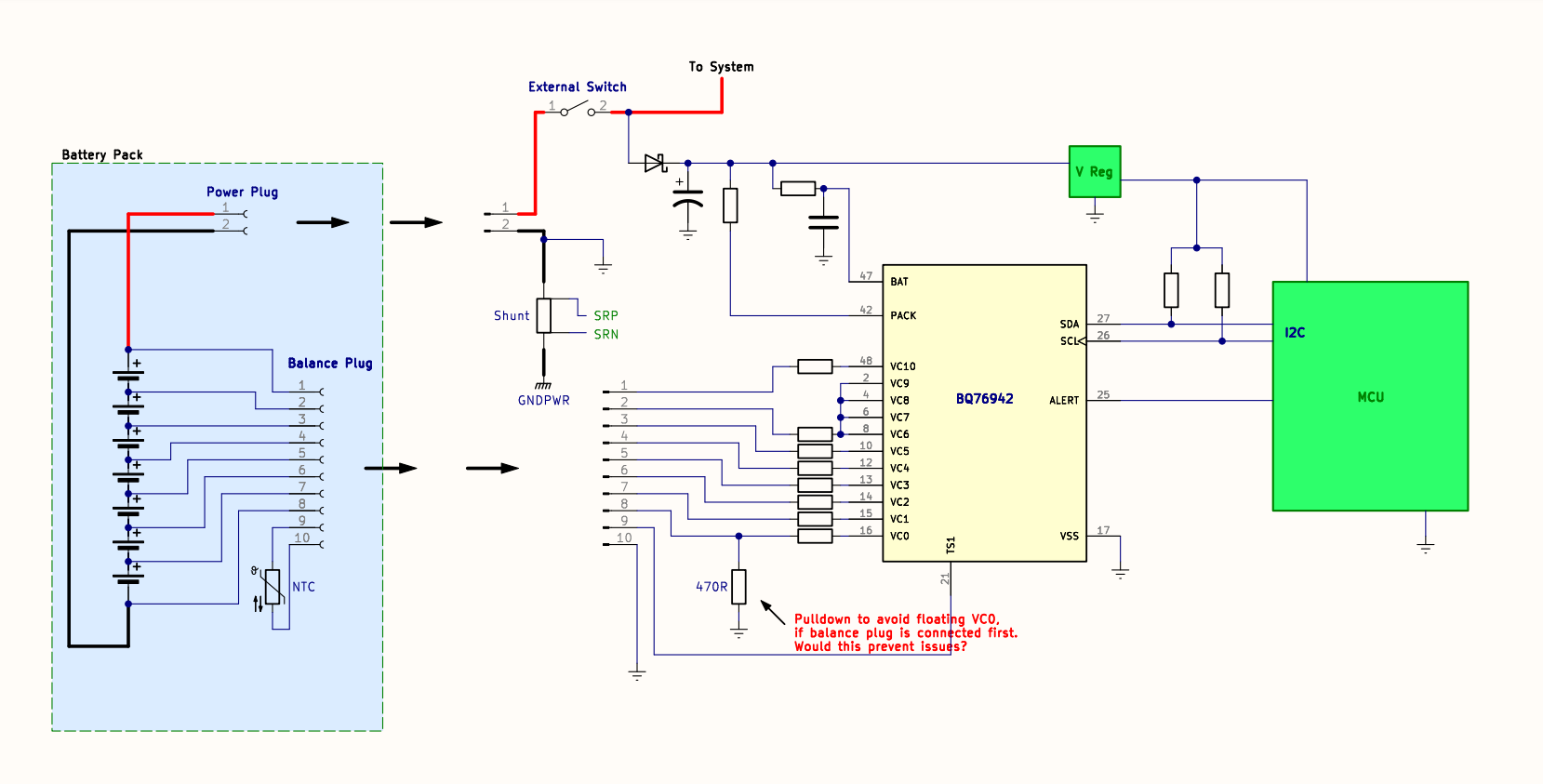
Hi, our design uses the BQ76942 to manage a 7S LiFePO battery pack.
The BQ76942 is on the product's PCB, while the battery pack (simply bare cells and a thermistor) can be removed and replaced. It is connected to the PCB by 2 plugs:
- A 2-pin POWER plug for carrying battery current, and
- A 10-pin BALANCE plug for connecting each cell to the BQ76942 (and also thermistor).
Here's the issue. As you can see in the simplified schematic below, if the BALANCE plug is plugged in before the POWER plug, the PCB's ground net is not yet connected to BAT-.
This means that VC0, VC1, VC2, etc, would be connected to battery cell voltages while the BQ76942 has a floating/undefined value at VSS.
The datasheet states that random cell attachment is only supported if voltage at VC0 is kept close to VSS. If the BALANCE plug is connected before the POWER plug, this condition will be violated.
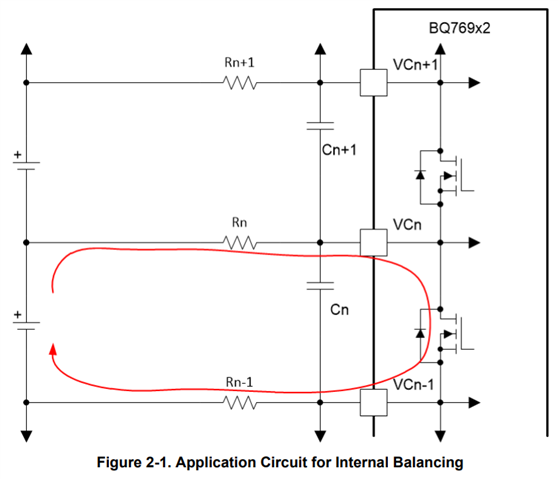
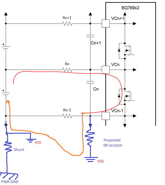
To avoid this, I added the 470R resistor shown below. I added a resistor (rather than a 0R jumper or net tie) because I was concerned about connecting to ground in 2 places (once the POWER plug is connected), creating a ground loop.
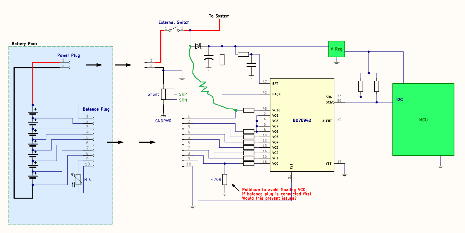
My question: is this a good solution? We've had some failures on prototypes of the below circuit (with the 470R resistor). The BQ76942 stops responding over I2C, so it seems to be dead, and we don't know what is causing this. Should the resistor instead be a 0R jumper (i.e. are my ground loop concerns not an issue?), or does the existing setup look fine and the failures are caused by something else?
Any other feedback/suggestions for this design is welcome. Thank you.


