This thread has been locked.

If you have a related question, please click the "Ask a related question" button in the top right corner. The newly created question will be automatically linked to this question.

BQ76952: BQ76952

Part Number: BQ76952
Other Parts Discussed in Thread: BQSTUDIO

Tool/software:

Hi,

I am using the BQ76952 in a 4 cell stack up with the cells at 1, 2, 3 and 16.  I have external balancing circuits with about 350mA.  Cells 1, 2 and 3 are balancing just fine but cell 16 seems not to balance even though BQ Studio displays that it is balancing. 

I have attached a word doc with the schematics.  The system supports up to 14 cells and with stuff options/variants we have a few SKU's of the board to support different battery stacks. The one in the schematic is for a 4 stack. 0 ohm resistors connect all the unused cells.

We used the recommend 100 ohm resistors (R24 et all) to reduce heat in the BQ76952 and have used a 12 ohm, 2W resistor for external balancing. We also used 20 ohms (R129) at cell 16 which was recommended by TI.

  Balancing.docx

Thanks!!

John

  • Hi John,

    I will look into your schematic and give you a response by tomorrow.

    Best regards,

    Thomas Rainey

  • Hi John,

    Can you send a waveform of the voltage at the VC16 pin?

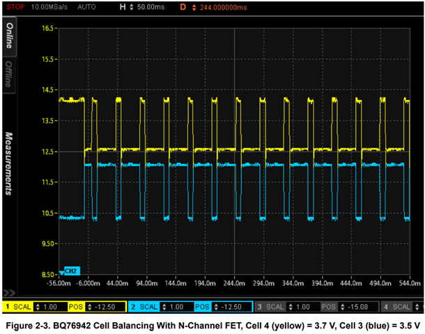
    The wave form of VC16 and VC3 should look similar to this if VC16 is balancing:

    Best regards,

    Thomas Rainey

  • Hi Thomas,

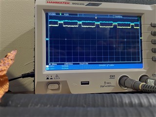
    Attached is the scope shot.  I would think that maybe we should be looking at VC15 since that is the signal that drives the FET?   Yellow is VC3 and Blue is VC16. Let me know if you want other scope shots.

    Thanks!!!! 

    John

  • Hello John Slight smile,

    Yes VC15 would be the best place to measure the voltage here.

    I assume that the Cell15 and Cell3 nodes connect to the positive side of Cell 3, correct?

    If that's the case, something I noticed from the schematic, is that you may be paralleling the resistance that is seen by the Q33 MOSFET. R135/R154 seem to be in parallel to me if Cell15/Cell3 connect to the same cell. I would suggest to remove R154 and see if works okay now.

    Best Regards,

    Luis Hernandez Salomon

  • Hi Luis! Good to hear from you. And good catch on the parallel resistors.  Due to the number of stacks the schematic supports, the schematic can get confusing!!  I'll give it a shot and let you know.  As always, most appreciated!!

    John

  • HI Luis,

    Got a few minutes to look at this. Scoped out the VC1, 2, 3 and 16 pins on the board I have and they are all toggling. VC1 and VC2 are inverted to one another as are VC3 and VC6 so that matches the scope shot sent by Tom.  So looking at the schematic, I noticed that the two resistors aren't in parallel because CELL3 and CELL15 are NOT connected and I think they should be.  So I removed R154 and tied CELL15 to CELL3.  I can still read the cell voltages properly but in relaxed mode, I don't see Cell 16 being balanced. It keeps losing charge. It is at 3.506 (was at 3.521) but the other three cells are 3.711, 3.884 and 4.067.

    I also notice that the Cell Balancing Active Cell register is always at 0x0005. I've seen it at 0x8002 before as well as 0x0005. I have VCELL Mode set to 0x8007 and the Cell Balance Max Cells = 2.  I measured the voltage across R129 (CELL16 and VC16) and it is 0 volts meaning it is not balancing. But then I started to think,  there is no path to charge the top battery and since the top battery is lower in voltage than the other three then it won't balance.  It will only balance if it's voltage is higher than VC3 (I think!). 

    I'll put the system in charge mode and see if when the batteries are charged that they balance or maybe I should discharge Cells 1-3 and charge Cell 16 and see if it balances the other cells.

    What do you think?

    Thanks!

    John

  • Or maybe when the FET is on then current flows up to the negative node of the battery on top?  Maybe I'm missing that.  If that is the case, then I'm just a little stumped on why Cell 16 is not balancing!!!

  • Hello John,

    When measuring the voltage across R129, did you measure with a probe? I think it is good to actually measure across R135, since this is the resistor that will cause the balancing MOSFET to turn-on. 

    But then I started to think,  there is no path to charge the top battery and since the top battery is lower in voltage than the other three then it won't balance.  It will only balance if it's voltage is higher than VC3

    Yes, if cell 16 is lower than the other three cells, it will not balance. The other cells may however balance in order to meet the level of the Cell 16 cell. Since this is passive cell balancing, the only way to balance is to burn power. You mentioned that this cell was at 3.5-V while the other cells were at higher voltages, so in that case this cell will never balance (autonomously at least).

    If you manually enable the balancing, it should be able to start balancing, you could try that as a quick test to see if balancing is possible at all for that cell.

    Best Regards,

    Luis Hernandez Salomon

  • Hi Luis,

    Do you agree that I must connect the CELL15 and CELL3 signals?  If cell 16 is lower than the other and it can't balance, then how would manually balancing them change this?

    I let the cells balance overnight is a relaxed state. The Cell Balancing Active Cells is toggling between 0x0004 and 0x0002.  I no longer see the most significant bit set (0x8000) while I do have VCELL mode set to 0x8007. So it seems as if that cell is not being autonomously balancing? Why would this be?

    Currently, I have CELL3 and CELL16 connected and I have removed R154 since they are now in parallel with the CELL signals connected.   BQStudio is reporting the correct voltages as I'm reading them with my DVM but I never see the 0x8000 bit set and the gate of Q33 is never driven.

    I am now charging the batteries and Cell 1 is 3.823V, Cell 2 is 3.875V, Cell 3 is 3.802V and Cell 16 is 3.792V.  Cell Balancing is staying at 0x0002 and I do see the gate of the FET at Cell 2 being driven. The gate of Cell 3 is toggling but inverted so Vgs is toggline between 0V and a negative voltage not turning the FET on. Vgs of Cell 2 is toggling between 0V and 1.8V. Vgs of the FET is  1.0V max so it is on.  

    It seems that something isn't right. I do have my balancing turn off voltage set to 10mV. Maybe that's a little too low? I did it so all would continuously balance. But it's bothering me a bit that the Cell Balancing Active cells is now stuck at 0x0002. I did change it to 75mV and now it stops and starts balancing but again, I only see 0x0002.

    Thanks!

    John

  • Hello John,

    Do you agree that I must connect the CELL15 and CELL3 signals?  If cell 16 is lower than the other and it can't balance, then how would manually balancing them change this?

    Correct, these two must be together. Because manually cell balancing would ignore cell voltages, so it would balance regardless of the actual cell voltage (As the host is assumed to make all the balancing decisions). This is just to check that the cell can balance (Since I thought that was the main concern/question).

    I am now charging the batteries and Cell 1 is 3.823V, Cell 2 is 3.875V, Cell 3 is 3.802V and Cell 16 is 3.792V. 

    I do believe that this is why Cell 16 is not balancing, it is the weakest/lowest voltage cell.

    Passive cell balancing will only bring down the cell voltage of cells, as it is only able to burn-off the additional charge from the battery. As Cell 16 is the lowest voltage cell, the other cells may balance to go down to the Cell 16 level, but they will not go lower than Cell 16. This likely would be true to any cell that has the lowest voltage among the cell string.

    Does that make sense?

    Best Regards,

    Luis Hernandez Salomon