This thread has been locked.

If you have a related question, please click the "Ask a related question" button in the top right corner. The newly created question will be automatically linked to this question.

TPS23755EVM-894: Components power consumption distribution for thermal simulation

Part Number: TPS23755EVM-894
Other Parts Discussed in Thread: TPS23755

Tool/software:

Hello,

We are desining a board using the reference design of TPS23755EVM-894.

We need to perform thermal simulation and we need the power consumption distribution over the TPS23755EVM-894 components.

Our design maximum consumption is 0.8A from the 12V nominal output.

I would appreciate if you can provide a power consumption distribution for consumption for components with 100mW or more.

Regards,

Yossi

  • Hi Yossi,

    Thanks for reaching out.

    TPS23755EVM-894 has ~86% efficiency at 0.8A and 12V when Vdd-Vss = 48V, fsw = 250 kHz. In this condition, the power loss is ~1.56W.

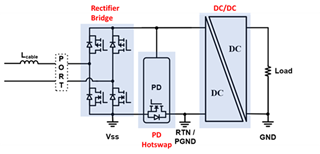
    The rectifier has ~0.7*2*11/48 = 0.32W

    The 2nd diode has ~0.8*0.6 = 0.48W 

    The TPS23755 and flyback transformer share the most of the rest of 0.76W

    What is your target power loss and temperature rise?

    For your reference below is a TPS23755EVM board thermal image under natural convection at 1A and 12V when Vdd-Vss = 48V, fsw = 500 kHz, which should have a higher temperature rise than your working condition. 

    Best regards,

    Diang

  • Hi Diang,

    Thanks for the quick and thorough answer,

    Just to make sure, when say rechtifier you refer to the two diode bridges D1 and D2 in the reference design?

    Also for the second diode, you refer to the diode on the 12V output, D3 in the reference design?

    Can you estimate the power on the controller TPS23755 and the flyback transformer? should I take half on each ~0.38W?

    Our Box should comply to maximum ambient temperature of 65C, and our engineering limit the maximum PCB temperature to 100C.

    BTW, Should there be a big difference in the power consumption due to ambient temperature? if yes can you estimate the wats per celsius?

    the diodes power consumption is reduced as the temperature gets higher, for example, so I can esimate that. I need your estimation for the controller and transformer.

    Regards,

    Yossi

  • Hi Yossi,

    Thanks for your reply.

    PoE PD design power loss mainly are from the rectifier bridge (D1 and D2 in the reference design), PD hotswap, and DC/DC.

    PD IC itself operating power is normally low (< 100 mW). But TPS23755 has integrated primary FET, which may cause higher power dissipation on the PD IC than others. It is hard to estimate the TPS23755 power loss when the FET is integrated. It may be easier to get the transformer power loss from the vendor Linkcom (https://www.linkcom.com.tw/en), and the calculate the PD IC loss by substracting the transformer loss. 

    The thermal test was done at ~25C ambient temperature. In this condition the rectifier temperature rise is ~40C and the PD temperature rise could be less than 40C.  Transformer core loss may reduce with temperature rise but copper loss may increase. You may also need to contact vendor Linkcom (https://www.linkcom.com.tw/en) for these information.

    Another thing you can try is getting a TPS23755EVM sample and run the thermal test at this environment. Please let me know if you want to order a sample and I can help you for that. 

    Best regards,

    Diang

  • Hi Diang,

    Thank you. I understand the complication.

    I'm waiting for a reply from Linkcom and also the EVB should arrive this week.

    I have few more questions regarding the design that I need for the layout editor.

    1. Does R34 necessary or I can connect VDD directly to VPD?
    2. Does R22 necessary?
    3. Whan is the expected power consumption of D13 (the 6.2V zener on VB)? would a 300mW zener instead of 500mW be OK?
    4. What is the minimum package size I can use for R5 (value 24 ohm)?

    Regards,

    Yossi

  • Hi Yossi,

    Thanks for your reply.

    1. Does R34 necessary or I can connect VDD directly to VPD?

    - Yes, you can directly short VDD with VPD.

    2. Does R22 necessary?

    - You can short R22 and directly connect CP with AUX winding. 

    3. Whan is the expected power consumption of D13 (the 6.2V zener on VB)? would a 300mW zener instead of 500mW be OK?

    - D13 avalanche energy is mainly related to C12 (bulk cap). For a 10uF cap, 300 mW Zener diode should be enough. 

    4. What is the minimum package size I can use for R5 (value 24 ohm)?

    - The snubber resistor power dissipation (size) depends on your voltage overshoot and temperature margin. The DC/DC design and layout take big impact for its size. I would assume 1206 is good for low temperature rise condition here. You may use 0805 if you can have a larger R5 resistance or smaller C13 capacitance, but it is with a tradeoff of the voltage overshoot increase on D3. 

    Best regards,

    Diang