This thread has been locked.

If you have a related question, please click the "Ask a related question" button in the top right corner. The newly created question will be automatically linked to this question.

LM74930-Q1: Behaviour during inverted battery insertion

Part Number: LM74930-Q1
Other Parts Discussed in Thread: LM74930, , LM5149

Tool/software:

Hello to All,

we are finishing a project of power supply 27V up to 13A.

To protect the cuircuit against the polarity inversion of batteries (2x 12V ermetic PB, normally 7-18Ah, but can be up to 65Ah), we are evaluating LM74930 chip.

But I have to ask clarification of behaviour of this chip in these operations step:
1) power supply is connected to 230Vac, the batteries are connected and the battery charger is charging the batteries
2) disconnect the batteries to replace it, by user
3) connect the new batteries but with polarity inverted, by user
4) the power supply advise this problem with any any damage (of batteries and of powers upply) and without any blackout on outpiut (because the are powered by 230Vac)
5) the batteries are re-connect in right manner, by user. And all it's ok.

QUESTIONS:
A) can this chip do this?
B) how this mechanism works?

Thank You and Best Regards
Federico Battaglin

  • Hi Federico,

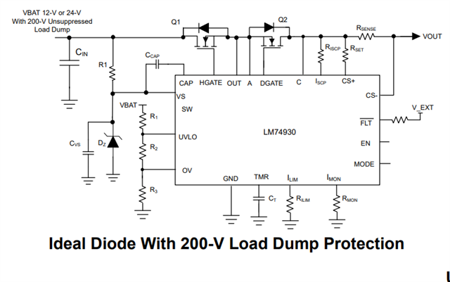
    LM74930-Q1 can protect from reverse polarity from VIN side only.

    If you planning to connect batteries at VOUT side and if they are connected in reverse, IC will be damaged.

    Talking about mechanism, when reverse polarity is connected at VIN side, device does not get its VS(PORR) voltage and device is basically in OFF state and the DGATE FET protects from reverse polarity.

    Regards,

    Shiven Dhir

  • Dear Shiven,

    in first, thank You for fast reply!

    No, no... the batteries are connected only on Vin.
    Yes, because on Vout is connected to electrical node: the mains supply sourse is from LM5149 protected by LM74700 and the output is protected by TPS48111 (against short circuit on output).

    Take in mind, that this electrical node, the voltage is the voltage of batteries charger, that is the voltageon output of power supply. So the current flow can be bi-drectional...

    After explain this, can mechanism save the power supply when user invert the batteries during the power on of power supply?

    Thank You and Best Regards
    Federico

  • Hi Federico,

    If batteries are connected at VIN, and charger is connected at VOUT. For current to flow from charger to battery, we first need to IC to be ON. That can only happen if VIN is in correct polarity. Hence, at first startup, If VIN = -12V (example), device wont power up. DGATE will be low and VOUT will be protected.

    Regards,

    Shiven Dhir

  • Ok...

    Suppose the batteries (24V), at the first turn-on have the right polarity and so the chip is ON. Then I disconnect batteries and re-connected inverted... Is the chip remeans in ON or turn-off when batteries disconnected?

    Federico

  • Please, any answer...?

  • Hi Federico,

    In that case, device will remain ON. With potential damage also.

    Regards,

    Shiven Dhir

  • So, if I connect the batteries in the right manner, then I disconnect meanwhile the battery charger works and I reconnect the batteries but inverted, this chip can potentail damage?

    Why it remain in ON state, if the VS goes down to 0 (zero) Volt?
    I understaood VS is the power supply and if there no voltage, the chip is in power off and all mosfet is in OFF.

    Why ship can potential damage?

    Federico

  • Hi Federico,

    While the batteries are charging, MODE pin is toggled which allows free flow of current. Because of which we have a power path to provide power to VS. Now even if batteries are disconnected, VS will still be active. 

    To avoid this, you might have to turn off the charger when batteries are disconnected with a BATT_MON maybe. After that if batteries are connected in reverse, controller will be off only.

    Regards,

    Shiven Dhir

  • Turn-off the batteries charger or toggle again the pin MODE to stop the free flow of current... I think...

    The main problem now is the BATT_MON... Does chip have the batt-mon or not?

    Best Regars
    Federico

  • Hi Federico,

    We do have an SW pin, but is going to monitor power rail. Which will read charger's output voltage when batteries are disconnected. You will have to sense VBATT by some means.

    Regards,

    Shiven Dhir

  • Uhm... it's need monitor the current flow and when the battery charger current down to the chip current, it means the batteries are disconnected. It's possible to monitor using the shunt, for example Rsens with internal OpAmp or external OpAmp + comparator that drives the MODE pin...

    Regards
    Federico

  • Hi Federico,

    Yes, this can be done toggle MODE pin or EN pin.

    Regards,

    Shiven Dhir