- Ask a related questionWhat is a related question?A related question is a question created from another question. When the related question is created, it will be automatically linked to the original question.
Tool/software:
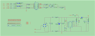
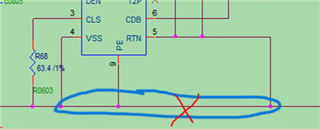
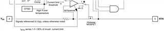
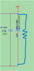
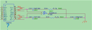
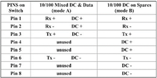
现用Ti的TPS2378做交换机的PD接口芯片,按下面原理图做成PD设备。接PSE设备后,无法给该PD设备供电(PSE设备是好的,可以给摄像机供电),量得PD接口处电压在DC3V左右。请分析下原理图有啥问题!
We are currently using Ti's TPS2378 as the PD interface chip and making the PD device according to the following schematic diagram. After connecting the PSE device, the PD device cannot be powered (the PSE device is good and can power the camera), and the voltage at the PD interface is measured to be around DC3V. Please help check if there are any issues with the schematic diagram!