This thread has been locked.

If you have a related question, please click the "Ask a related question" button in the top right corner. The newly created question will be automatically linked to this question.

TPS25946: Startup Questions

Part Number: TPS25946

Tool/software:

Hi expert,

Customer used TPS259460 with application 12V(typ.) and 5.3A continuous maximum. 

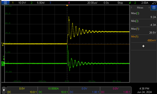
Here is a test waveform during adapter plug-in.  Some questions:

1. they have TVS at input, why the input voltage still go up to 28.5V over the absolute rating? 

2. they set current limit at about 5.9A but why we still see current go to 9.2A? Is there an absolute maximum current rating for the TPS259460? Cause I see the DS spec internally limited.

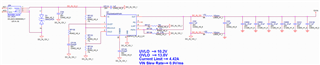
Schematic: TPS259460ARPW_circuit.pdf

Thanks,

Allan

  • Hi Allan,

    1. Can you share TVS part number (I am asking this cause schematic have DNI written next to TVS)

    2. Transient current can go to higher level. Here we can see that current is going till 9.2A which is less than Fixed Fast trip threshold of 22A, so device is not fast tripping which is expected behavior.

    Best Regards,
    Arush  

  • Hi Arush,

    1. Please find updated schematic. Customer do have TVS on it. The part number is SMAJ24CA. Please help clarify if it's still reasonable or how to resolve it?

    2. Got it. 

    Thank you.

    Allan

  • Hi Allan,

    They can add some more caps at the input to reduce this ringing. 

    The reason for 28.5V max is the breakdown voltage of the TVS diode. This is fine since the abs max of device is 28V. This ringing is caused due to higher path impedance. 

    Best Regards,
    Arush

  • Hi Arush,

    Still don't quite understand why 28.5V is fine for the device which the absolute maximum rating is 28V? Could you please explain more about it?

    Thanks,

    Allan

  • Hi Allan,

    Yes, you are right in pointing out that it is violating the abs max limit. Earlier I mentioned that it is fine because it is a transient violation very near the limit. I checked again and I think if they change the TVS diode to SMAJ22CA, this can also be resolved.

    I apologies for creating confusion and thank you for pointing this out.

    Earlier when I mentioned about adding more caps at input, I meant increasing input decoupling cap also. Did they retest with increased caps? Are they still seeing ringing? 

    Best Regards,
    Arush

  • Hi Arush,

    I adding a 10uF capacitor at the input or changing the TVS to SMAJ22CA did not improve the measurement results.
    Please respond to the following two questions:

    01. Do you have any other suggestions for improvement?
    02. Attached are the test results for your reference.The duration of over 28V is approximately 24ns. Does this interval comply with the specifications? If so, what is the allowable range according to the specifications?


    Best regards,
    Benny

  • Hi Benny,

    Did you add the capacitor near the device or there is some distance from the device. It is best to add it near the device. Regarding the >28V for 24ns, I will have to get it verified from the designer of this part.

    By any chance, are you using long wires at input? This wire inductance can cause these high transients. 

    Best regards.
    Arush 

  • Hi Arush,

    Regarding your inquiry, here are the responses:
    01. The 10uF capacitor is positioned very close to the chip input terminal.
    02. Short wires were used for the measurements, not long ones.

    Regarding the issue you asked about, occasionally the voltage may slightly exceed the current measured result of 28.1V, sometimes reaching 28.5V.
    However, it cannot be guaranteed that these occurrences are precisely spaced every 24ns, hence the query about permissible margins.

    Best regards,
    Benny

  • Hi Benny,

    Regarding the issue you asked about, occasionally the voltage may slightly exceed the current measured result of 28.1V, sometimes reaching 28.5V.
    However, it cannot be guaranteed that these occurrences are precisely spaced every 24ns, hence the query about permissible margins.

    Makes sense. This will take some time.

    02. Short wires were used for the measurements, not long ones.

    I thought this is the primary cause of transients but you are saying short wires, so we won't be able to optimize here. 

    01. The 10uF capacitor is positioned very close to the chip input terminal.

    This should help but it isn't. I am not sure why it isn't helping. Are you placing the cap at CP110 pads. Can you place some more caps here just to check if that is helping.  

    Can we also try this experiment with higher dvdt capacitor. like 10nF or something similar. That should reduce the startup speed which will reduce the inrush current and lower transients. 

    Best Regards,
    Arush

  • Hi Arush,

    01. The newly added capacitor has been placed extremely close to the IC input.
    02. Attempting to increase to 10uF*2 resulted in a current greater than 22.2A, likely causing damage to the IC. It is not recommended to use such a high capacitance value. (See Figure 1)
    03. Changing the dvdt capacitor (CP108) to 10nF resulted in a measured voltage higher than the original value. (See Figures 2 and 3)
    Figure 1


    Figure 2

    Figure 3

    Best regards,
    Benny

  • Hi Benny,

    What is the load you are applying? 

    Best Regards,
    Arush

  • Hi Arush,

    The load is my DUT system.

    Best regards,
    Benny

  • Hi Benny,

    Can you test the eFuse with some e-load to check if this behavior carries over. You can use CR mode. (12V/5.3A = 2.2Ohm load.) 

    Best Regards,
    Arush