This thread has been locked.

If you have a related question, please click the "Ask a related question" button in the top right corner. The newly created question will be automatically linked to this question.

LMG2100R044: LMG2100R044 Thermal performance

Part Number: LMG2100R044
Other Parts Discussed in Thread: LMG2100R026

Tool/software:

Hi, I have certain question related to LMG2100R044.

Requirement to disable the gate driver:

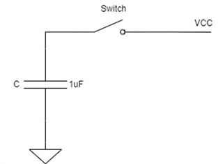
Can we use VCC (5V) cutoff to enable and disable the gate driver. Our requirement is to switch off gate driver IC when there is any safety related fault. One of the faults is short circuit of GaN FET, in this case we need to shut down gate driver within 2us after asserting fault signal to gate driver IC. Is VCC cutoff is good way to make sure output GaN FET is turned off quickly within 2us? Or we need to have different strategy for this e.g. have switch on input PWMs to gate driver that will be opened (PWM state 0) in short circuit fault assertion.


Thermal Characteristics of LMG2100:

We are using this part in BLDC motor driver application. We will have LMG2100 for each three phases of the motor. Our switching frequency is 50kHz and supply voltage will be maximum 36V. Driver shall supply 15Arms continuous to motor and peak of 30 - 35Arms for 4-5 sec max.  Can LMG2100 will meet this requirement. We would be using heat sink, and that heat sink will be mounted to metal enclosure. Our ambient temperature would be max 50 – 60 degrees C. What is your recommendation for better thermal strategy? Is this right part or do you have any other suggestions.

  • Hi Rohit, 

    Thanks for your question. We will have a member from our MV GaN team respond in the next day.

  • Hi Rohit,


    Opening the gate driver PWM would have reaction time of 35ns-50ns(propagation delay) which fits in your requirement. Let me get back to you on shutting of VCC supply off and pros/cons of it.

    For your system requirement, as 35A peak current is close to the abs. max rating of LMG2100R044, you can evaluate the system with LMG2100R026 which 2.6mohm version of LMG2100 with abs. max current 53A. This would be a better option for your use case. We are sampling this device right now, and will be launch on ti.com in later July.

    Best Regards,
    Madhur

  • Thanks for reply.

    We are considering VCC supply off for gate driver, if we get to turn off gate driver off within 2-3us it will be good. If this does not work, then we have to go with PWM switch off strategy.

    We are currently doing schematic design for this project, 53A part looks good, can you share datasheet. Can you tell when LMG2100R026 will be in production? 

    So, LMG2100R044 would not handle 35A current for short duration even with heat sink and thermal consideration?

    Thanks,

    Rohit 

  • Hi Rohit,

    If you keep switching after the fault and turn off VCC, the FETs are turned off only after UVLO of LMG2100 triggers (after VCC cap voltage dropped to 3.6V). If you have 1uF cap on VCC pin, after shutting off VCC, it will take (1uF * 1.4V) /  7.5mA = 186us to discharge VCC from 5V to 3.6V UVLO. 
    (Here, 7.5mA is VCC operating current) 
    So, turning off VCC doesn't suit your need. You should switch off PWM or pull HI/LI pins low at fault condition.

    LMG2100R026 is a pre-release device and similar to LMG2100R044 just change of GaN FETs. We don't have a datasheet right now, but can share any specific info if you want. The device is sampling right now, and will be released in Jan 2025.

    LMG2100R044 can handle 35A of current as long as the junction temperature is below 125deg with the heatsink and sufficient cooling.


    Best Regards,
    Madhur

  • Hi Madhur,

    Thanks for reply. We have design freeze by end of July so if we want to go with LMG2100R026 now then we need info on its specs, symbol, footprint etc. LMG2100R026 looks good but need these details to make decision soon. Release in Jan 2025 is a production release, right?

    Regarding VCC cutoff strategy to reduce the capacitor discharge time, can i just put switch after capacitor as shown below. Switch and capacitor will be placed close to the VCC pin. In this case do you think that 2-3us GaN switch cuttoff is achievable. 

    Thanks,

    Rohit Chauhan

  • Hi Rohit,

    Please wait for couple of weeks for the details, this will be released on ti.com soon.

    For the VCC arrangement, yes it will work but try to place capacitor close to the pin. Also, add a 3ohm resistor to VCC path for slew rate control of the bottom FET.

    Best Regards,
    Madhur

  • Thanks for reply, it will help me. I will close this topic now unless I have any further question.