This thread has been locked.

If you have a related question, please click the "Ask a related question" button in the top right corner. The newly created question will be automatically linked to this question.

UCC21222-Q1: External Active Miller Clamping circuit is not working properly

Part Number: UCC21222-Q1

Tool/software:

Hello, I have a question regarding Active Miller clamp circuit for UCC21222-Q1. I am doing a 50-kW Boost converter and applying the Active Miller clamp circuit for high-side (HS) MOSFET as follows:

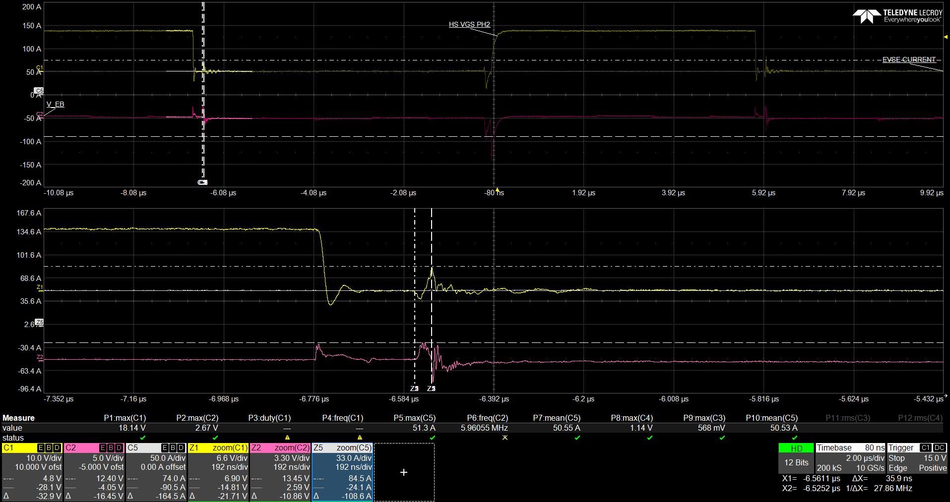
I found that the clamp circuit works but the voltage glitch is still high (6.9V at 20kW):

I guess because of the turn-on delay problem, even though Q21 is closed, the VGS voltage (which is also the VEC voltage of Q21) cannot discharge immediately.

What do you think about this issue? Is there any way to help VGS discharge faster? Or is there another clamp circuit that is more effective? 

Thank you!

Best regards,

Nhan

  • Hi Nhan,

    Thank you for reaching out on E2E.

    The first thought that comes to mind is to make sure the loop formed by the Miller clamp is as tight as possible. If this loop inductance is not minimized enough, the inductance can add impedance to higher frequencies.

    Another important factor is the Rdson of the Miller clamp and how variable it is with certain conditions. Make sure that the Miller clamp is able to sink the sufficient amount of current without saturating.

    Hope this helps. 

    Regards,

    Hiroki