


Tool/software:
Hi Team,
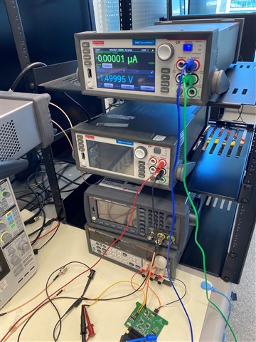
My name is Vinod and I work at Meta in the hardware engineering team. I am working on bringing up the PMIC load board that we are planning to use for testing our PMIC. There are a couple of issues we are running into, if you can please help with explanation/debugging that would be great. Just so you know, I tried asking this question in the E2E forum but it is not letting me post my question. I have attached images of the setup, the setup is as follows: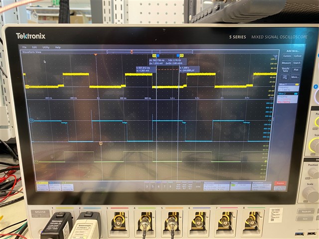
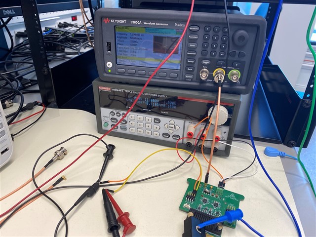
1. 50mV control signal pulse, frequency - 1 Hz is being configured from AWG and connected to J1, the switch is set to the right position to enable parallel mode
2. A Keithley SMU is connected as a source (set to 1.5V) to measure current and is connected to Load1 and GND
3. Another Keithley SMU is connected to Ch1, J2 to measure voltage. Also, the scope probe is connected to the same leads to observe the time domain voltage waveform
4. The current probe is connected to load1 and gnd to observe the current waveform on the scope
5. The power supply is configured to +11 and -11 volts as recommended and connected to J5 power terminal.
Issues:
Issue #1:
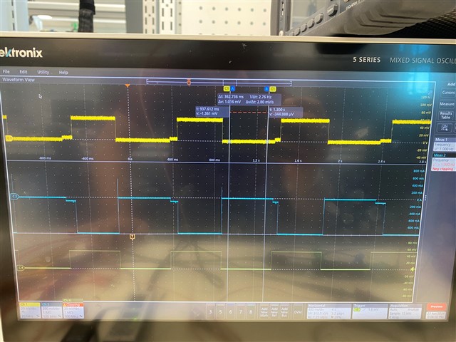
As you can see the waveform, the voltage waveform (J2 output - Color yellow) and Current waveform (Blue Color) it has a weird step to it and it also seems to be periodic, almost a step-down ramp of equal to 100mA which is significant. We are trying to debug and trying to explain the possible reasons, have you seen something like this on your setup and can you help us with the reason and/or debug? Let me know if you have further technical questions or if it is possible to schedule a virtual call?
Issue #2:
If we compare the rise time of the voltage waveform (yellow) and rise time of the current waveform (blue color) there seems to be a significant difference. If we zoom in, we can confirm that the rise time of the "voltage" waveform is close to 200ns but if we look at the "current" waveform the rise time is close to 3us. In the setup guide you show the rise time to be as fast as 80ns for current that goes from 0-8A. We have a current probe that is capable of measuring ns time and we have extremely small leads on the pads, i even tried reducing the length thinking that is contributing to the delay but no change in the current waveform. Can you please check and also let me know about this?
Please let me know, I would greatly appreciate your response ASAP.
Thanks and Regards,
Vinod
