This thread has been locked.

If you have a related question, please click the "Ask a related question" button in the top right corner. The newly created question will be automatically linked to this question.

TPS543C20: RVFT

Part Number: TPS543C20
Other Parts Discussed in Thread: TPS543B20

Tool/software:

TPS543C20 failure after 3-6 months of operation, HS_FET and LS_FET burn out and output short-circuit.

Help us analyze the possible causes of the two MOS tubes burning. Application environment:Input:12V,Output:1V, Average current 17A, Peak current 19A.

Below is my schematic design:
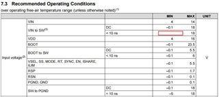
SW:

  • Hello, 

    It looks like the SW ringing is peaking above our maximum recommended operating condition of 18V on SW, so damage to the FETS is not surprising. This is likely due to not having a high frequency bypass capacitor at the input pins. We recommend to add a 2.2nF-10nF capacitor as close to the PVIN pins as possible to help reduce this. This usually offers enough margin, but if further reduction is needed a snubber circuit can be added to SW.

    Best regards,

    Britton

  • Hi Jones,

    The maximum SW is 20V, the recommended value is 18V, the design is in a critical state, but it does not exceed the maximum, will this cause internal HS and LS damage? The current probability is 1%。

    The suggestion in the PVIN datasheet is 10nF-100nF. In the design, I placed a 1uF capacitor. During the debugging process, I changed a 47nF capacitor, which did not affect the ringing of SW.

    Is there any direction that can help us figure out why the chip failed

  • The maximum recommended operating condition is 18V. Although the absolute maximum is 20V, continuous operation above the operating maximum may damage the FETs. The datasheet does mention 10nF-100nF but in my experience, 2.2nF-10nF for a high frequency bypass capacitor is the best starting value to see improvements, this must be placed directly next to the PVIN pins. I reviewed the schematic and I do have recommendations that would improve the design: The first is the total capacitance of ~400uF seems very low. This design would benefit from about 10x the effective output capacitance. Under the current conditions, I would expect very large overshoot and undershoot under any change in load. Though, this is not as directly related to fet damage as the SW node ringing. Without bringing the ringing in control and increasing the effective output capacitance, I can not guarantee no issue over long term. Once those issues are addressed, the next step would be to double check the layout. 

    Best regards,
    Britton

  • Hi Britton,

    I understand,but  what I want to say is that the chip failure only occurred in one of our projects, and our design is universal. Is there any other direction to investigate this problem。

  • The 2 sources of FET damage are (1) exceeding the device voltage limits and (2) exceeding the current limits. Given that the maximum load is 19A and the current limit is set appropriately, I do not expect current to be the source of the damage. That said, we know from the attached screenshot that the voltage is quite close to the absolute maximum. If any input transient or load transient occurs on this rail, we would expect the voltage exceed the abs max for the device. One line of investigation that we can pursue is to measure PVIN directly at the pins so that we can see a measurement of PVIN-SW, which impacts the HS fet. You mentioned that this only occurred in one of the projects but the design is universal, are there any other differences that might exist between proejcts, even if they are minor layout or BOM differences? 

    Given that this is not affecting all devices, my hunch is that a load or line transient occurred on this rail and caused a SW spike that exceeds the abs max. The last thing we can do is investigate the top markings of the device to determine if there have been any other quality issues related to that lot (please attach pictures), however this is extremely unlikely and this case is most likely related to exceeding the voltage rating of the fets.

    To prevent the issue from occurring in future, I recommend a full layout and schematic review which I am happy to help with.

    Best regards,

    Britton

  • Britton,

    The following is the waveform of PVIN to SW measured by us, and this voltage margin is still available.

    The PCB layout is as follows. Please also help check whether there are any design defects:

  • Hi Jiong, 

    I reviewed the layout and do not have any concerns. My design concerns are all on the schematic side (mentioned above). 

    The PVIN-SW voltage is well within rating. I still believe it is correlated with the SW-GND abs max. The ringing is dangerously close to the abs max value and any transient may have caused the voltage to go above 20V. This would damage the LS Fet and when one FET gets damaged, there is usually a 'cascading failure' where the HS Fet becomes damaged shortly after due to dumping too much current through the LS FET. I believe that if you resolve the SW node ringing then there will not be risk of FET damage in future cases.

    Best regards,

    Britton

  • Hi Britton,

    Addition, the ringing is close to the SW-GND abs max,how serious will its impact on the Mosfet be, what is the probability of the chip being damaged under such conditions, and whether the chip will not be damaged if it does not fail after stable operation for a period of time.

  • Any temporary breach of the abs max value may result in serious mosfet damage. Since the pictured value is so close the abs max, any transient may have caused the value to exceed the abs max, the likelihood of this is high. The chances of a device being damaged are low if that device has been operating successfully within the recommended operating values for an extended period of time.

    Best regards,

    Britton

  • Hi Britton,

    Can the screen print on the TOP of the chip interpret the DC of the chip?

  • Hi Jiong,

    I was able to confirm this lot code in our internal system. What do you mean by interpret the DC of the chip?

    Best regards,

    Britton

  • Hi Britton,

    Can the DataCode of the chip be known from the screen printing on the chip surface, especially what does the screen printing in the red box mean?

  • Hi Jiong,

    Yes the code can be determined by the markings, we refer to it as the Lot Trace Code. The marking "TI" is just the company name. The "13I" refers to Year (1=2021), Month (3=March), and a unique identifier ("I") 

    Best regards,

    Britton

  • Thanks,Britton,

    I have one more question:Why does the VIN to SW described in the datasheet have no limit to the negative voltage ( MIN ), which is also written in other datasheet like TPS543B20.

    The following is the TPS543C20 sdatasheet:

  • Hi Jiong, 

    Likely due to an oversight. Using the TPS543B20 as an example, you can see that the 10ns for VIN-SW is comparable to SW-PGND. I cannot give the confirmation as an official spec without going through internal process, but can make a reasonable assumption given the datasheets for the other devices in this family.

    Best regards,

    Britton