


Tool/software:
I have a design with the Schematic, BoM and layout largely lifted from the TPS55289 Buck-Boost Converter Evaluation Module User's Guide, https://www.ti.com/lit/pdf/slvucf2. After power up i2c access is met with a NAK (which is the equivalent of the part not responding). The boards are machine assembled and I've buzzed on two boards for shorts and found no issues. Two boards both behave in the same manner. In this application the input power is a 5V/3A rated supply and the maximum expected load is 0.8A @ 7V. VIN. 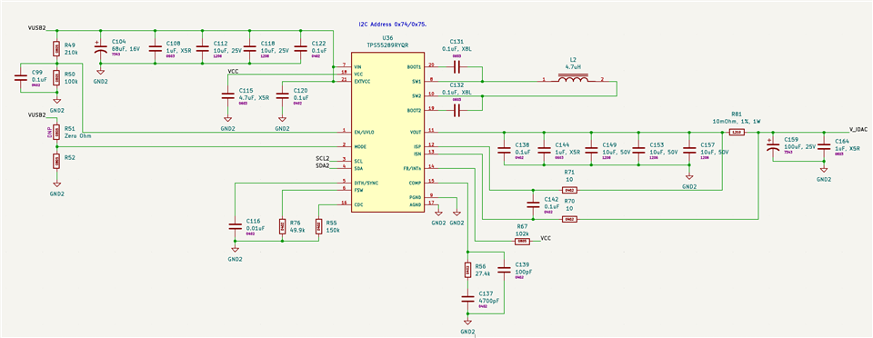
I've verified the voltages on:
VIN (4.92V)
EXTVCC (4.92V)
VCC (4.90V)
EN / VLDO (1.77V)
MODE (0V)
I've verified all of the timing requirements for the i2c interface as easily being met. I'm running the bus at 100kHz. Here's a scope trace of the first byte (address = 0x75 + write bit: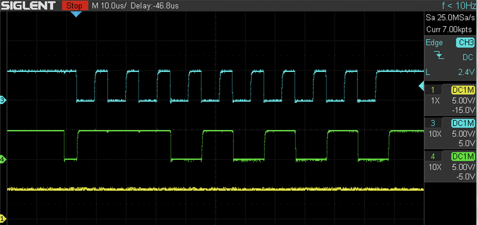
Decoded version on logic analyzer as a sanity check: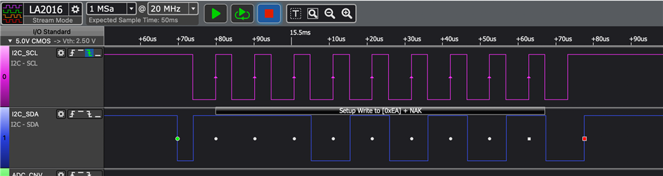
Could you please provide a list of potential other issues that would prevent the device from responding or other items to check to determine the state of the device?
