This thread has been locked.

If you have a related question, please click the "Ask a related question" button in the top right corner. The newly created question will be automatically linked to this question.

EMB1499Q: EMB1428Q & EMB1499Q - charging only lasts for 2 seconds (instead of 8 seconds) before shutting down

Part Number: EMB1499Q
Other Parts Discussed in Thread: EMB1428Q

Tool/software:

Hello,

I would appreciate your input on an issue I've encountered today.

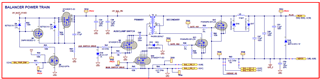
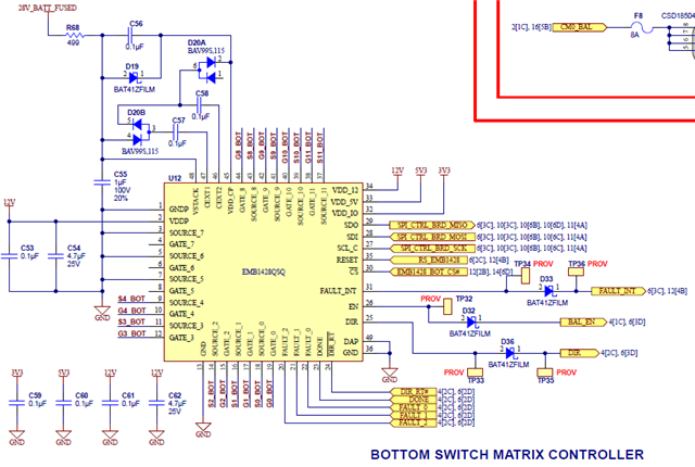
I'm utilizing the EMB1428 and EMB1499 chips for cell balancing. According to the datasheet, "the EMB1499Q features an integrated watchdog timer that automatically powers down the forward converter after 8 seconds of uninterrupted operation. To maintain charging or discharging a cell for more than 8 seconds, the microcontroller must send a stop and start command at least once every 8 seconds."

However, I've observed that charging only lasts for 2 seconds (instead of 8 seconds) before shutting down, whereas the discharge cycle completes the 8 seconds without any problems.

Even when I attempt to send STOP & START commands every 1 second to sustain the charging cycle, it halts at 2 seconds, pauses for 1 second, and then resumes the charging cycle. It consistently stops at 2 seconds with at least a 1-second idle period before restarting.

Additional observations: The charging cycle operates continuously for 8 seconds when VSET is set to 1V or less, but fails to do so for VSET values greater than 1V. 

But as per datasheet "Supported values for VSET range from 1V to 2.2V".

My equation (FYI):
DAC Output = (desiredVoltage / vref) * (resolution - 1)
vref = 3.3V, resolution = 2^8 => 256, desiredVoltage = 1.0V

I kindly request your advice on this matter.

  • Hello,

    Thank you for bringing up the questions. I am going to get back to you when I have more information on this device.

    Best,

    Zachary

  • Hello,

    Balancing current is set using VSET and the secondary sense resistor. Which value are you using for Rsense? We also recommend VSET to be set to 2v. When starting cell balancing, is voltage on VSET maintained? Is this an issue that you see on only 1 device or multiple devices?

    Thanks,

    Zachary

  • I initially set the VSET to 2V as recommended, but I encountered an issue where the charging only lasted for 2 seconds. To troubleshoot, I explored other VSET values. As I mentioned earlier, the problem occurs when the VSET exceeds 1V. The VSET value remains constant during runtime and consistently stays at 2V. I’m using a 10m Ohm Rsense. Currently, I’m testing this on one device; I haven’t checked the other one yet.

    Feel free to refer to the schematic of my system below:

  • Thank you for your schematic.

    Are you able to monitor the EN and DONE pins during an operating cycle? Is EN toggled LOW and DONE toggled HIGH after 2 seconds? Are any FAULT pins being asserted after the cycle? Furthermore, 8 seconds is the maximum operating cycle length before watchdog shuts off the forward converter. This doesn't necessary mean that a cycle needs to last 8 seconds. While VSET = 1V is technically within the operating conditions of the device, our testing was done with VSET = 1.2 - 2v. It seems at 1V, watchdog is manually shutting off the operating cycle.

    Best,

    Zachary

  • Yes, I successfully observed the EN and DONE pins behavior. The charge cycle completes successfully in 2 seconds, with EN going Low and DONE switching to High. Additionally, I checked the fault bits and consistently received 0xA0 for stop, 0xA2 for initiating a charge cycle on cell 2, and 0xAA for starting a discharge cycle on cell 2, without detecting any faults.

    My goal is to maintain the charging process for 60 seconds, intending to alternate between stop and start commands every 5 seconds to sustain the charging activity. However, the attempt to keep the charging ongoing with a 5A current for 8 seconds, as specified in the datasheet, by setting VSET to 2V using a 10mOhm resistor to achieve approximately 4.6A, does not succeed. Do you have any suggestions?

  • I've continued testing cell balancing more in my setup and now I am noticing that incorrect data is being transmitted from the EMB1428 to the STM microcontroller for the STOP and START commands, resulting in the failure of charging and discharging operations. Now, the EMB1428Q chip doesn't perform cell balancing at all, instead it sends incorrect data to microcontroller. I'm unable to interpret the DATA sent by the EMB1428, as it is not specified in the datasheet. Could you please explain the meaning of the data on the MOSI line from the table below?

    Master -  STM32F469
    Slave -  EMB1428Q
    Commands:
        STOP - 0x00
        START (Charge Cycle, Cell 2) - 0x20
        START(Discharge Cycle, Cell 2) - 0xA0
    MOSI MISO
    (response from EMB1428)
    MOSI MISO
    (response from EMB1428)
    0x00 0xFF
    0xA0 0xFF
    0x00 0xFF 0xA0 0xDF
    0x00 0xFF 0xA0 0xDF
    0x00 0xFF 0xA0 0xFF
    0x00 0xFF 0xA0 0xFF
    0x00 0xFF 0xA0 0xFF
    0x00 0xFF 0xA0 0x5F
    0x00 0xFF 0xA0 0xFF
    0x00 0xFF 0xA0 0xDF
    0x00 0xFF 0xA0 0x5F
    0x00 0xFF 0xA0 0x5F
    0x00 0xFF 0xA0 0xFF
    0x00 0xFF
    0x20 0xFF
    0x00 0xFF 0x20 0xFF
    0x00 0xFF 0x20 0xFF
    0x00 0xFF 0x20 0xD0
    0x00 0xFF 0x20 0xD0
    0x00 0xFF 0x20 0xFF
    0x00 0xFF 0x20 0xD1
    0x00 0xFF 0x20 0xFF
    0x00 0xFF 0x20 0xFF
    0x00 0xFF 0x20 0xF4
    0x00 0xFF 0x20 0xF0
    0x00 0xFF 0x20 0xFF
    0x00 0xFF
    0xA0 0x9F
    0x00 0xFF 0xA0 0xFF
    0x00 0xFF 0xA0 0x5F
    0x00 0xFF 0xA0 0xDF
    0x00 0xFF 0xA0 0xDF
    0x00 0xFF 0xA0 0xFF
    0x00 0xFF 0xA0 0xFF
    0x00 0xFF 0xA0 0xFF
    0x00 0xFF 0xA0 0xFF
    0x00 0xFF 0xA0 0xDF
    0x00 0xFF 0xA0 0x5F
    0x00 0xFF 0xA0 0xDF
    0x00 0xFF
    0x20 0xC0
    0x00 0xFF 0x20 0xD0
    0x00 0xFF 0x20 0xDF
    0x00 0xFF 0x20 0xF0
  • Hello,

    Can you provide logic waveforms for the mosi miso lines. I am not quite sure what the table is showing. Can you also measure VDDio, VDD5v, and VDD12v?

  • Thank you for your reply. I'll record the waveforms and share them with you later.

    I've updated the table to provide a clearer perspective on the situation. I believe this updated table will provide you with more comprehensive details and enhance your understanding of my setup. Please provide your feedback if this info is not sufficient:

    I measured the VDDio, VDD5v and VDD12v and the voltages are as expected shown in the schematic below.

    Updated table below:

    Master -  STM32F469
    Slave -  EMB1248Q
    Commands:
        STOP - 0x00
        START (Charge Cycle, Cell 2) - 0x20
        START(Discharge Cycle, Cell 2) - 0xA0

    Requirement:  charging/discharging process for 60 seconds each, intending to alternate between stop and start commands every 5 seconds to sustain the charging/discharging activity.

    Every 5 seconds, the operations listed in the table below are carried out to maintain continuous charging or discharging for a duration of 60 seconds. After this period, the process switches between charging and discharging modes every 60 seconds.
    TimeStamp
    (in Secs)
    CMDs MOSI (from STM uC) MISO
    (response from EMB1428)
    CMDs MOSI (from STM uC) MISO
    (response from EMB1428)
    Initiate Discharge Mode for CELL #2 (Stop & Start commands every 5 seconds to maintain charge or discharge cycle)
    0 START DISCHARGE 0xA0 0xFF
    0+5 STOP 0x00 0xFF START DISCHARGE 0xA0 0xDF
    0+10 STOP 0x00 0xFF START DISCHARGE 0xA0 0xDF
    0+15 STOP 0x00 0xFF START DISCHARGE 0xA0 0xFF
    0+20 STOP 0x00 0xFF START DISCHARGE 0xA0 0xFF
    0+25 STOP 0x00 0xFF START DISCHARGE 0xA0 0xFF
    0+30 STOP 0x00 0xFF START DISCHARGE 0xA0 0x5F
    0+35 STOP 0x00 0xFF START DISCHARGE 0xA0 0xFF
    0+40 STOP 0x00 0xFF START DISCHARGE 0xA0 0xDF
    0+45 STOP 0x00 0xFF START DISCHARGE 0xA0 0x5F
    0+50 STOP 0x00 0xFF START DISCHARGE 0xA0 0x5F
    0+55 STOP 0x00 0xFF START DISCHARGE 0xA0 0xFF
    0+60 STOP 0x00 0xFF
    60 Seconds cycle complete - Initiate Charge Mode for CELL #2
    0 START CHARGE 0x20 0xFF
    0+5 STOP 0x00 0xFF START CHARGE 0x20 0xFF
    0+10 STOP 0x00 0xFF START CHARGE 0x20 0xFF
    0+15 STOP 0x00 0xFF START CHARGE 0x20 0xD0
    0+20 STOP 0x00 0xFF START CHARGE 0x20 0xD0
    0+25 STOP 0x00 0xFF START CHARGE 0x20 0xFF
    0+30 STOP 0x00 0xFF START CHARGE 0x20 0xD1
    0+35 STOP 0x00 0xFF START CHARGE 0x20 0xFF
    0+40 STOP 0x00 0xFF START CHARGE 0x20 0xFF
    0+45 STOP 0x00 0xFF START CHARGE 0x20 0xF4
    0+50 STOP 0x00 0xFF START CHARGE 0x20 0xF0
    0+55 STOP 0x00 0xFF START CHARGE 0x20 0xFF
    0+60 STOP 0x00 0xFF
    60 Seconds cycle complete - Initiate Discharge Mode for CELL #2
    0 START DISCHARGE 0xA0 0x9F
    0+5 STOP 0x00 0xFF START DISCHARGE 0xA0 0xFF
    0+10 STOP 0x00 0xFF START DISCHARGE 0xA0 0x5F
    0+15 STOP 0x00 0xFF START DISCHARGE 0xA0 0xDF
    0+20 STOP 0x00 0xFF START DISCHARGE 0xA0 0xDF
    0+25 STOP 0x00 0xFF START DISCHARGE 0xA0 0xFF
    0+30 STOP 0x00 0xFF START DISCHARGE 0xA0 0xFF
    0+35 STOP 0x00 0xFF START DISCHARGE 0xA0 0xFF
    0+40 STOP 0x00 0xFF START DISCHARGE 0xA0 0xFF
    0+45 STOP 0x00 0xFF START DISCHARGE 0xA0 0xDF
    0+50 STOP 0x00 0xFF START DISCHARGE 0xA0 0x5F
    0+55 STOP 0x00 0xFF START DISCHARGE 0xA0 0xDF
    0+60 STOP 0x00 0xFF
    60 Seconds cycle complete - Initiate Charge Mode for CELL #2
    0 START CHARGE 0x20 0xC0
    0+5 STOP 0x00 0xFF START CHARGE 0x20 0xD0
    0+10 STOP 0x00 0xFF START CHARGE 0x20 0xDF
    0+15 STOP 0x00 0xFF START CHARGE 0x20 0xF0
  • Hello,

    Since Zach is out-of-office, I was assigned to help you with this request. Allow me to catch up with what you were previously discussing and I will get back to you within the next days.

    Thanks for understanding!